
Pressure-reduction drying system and method for substrate

A drying system and drying method technology, applied in the direction of surface pretreatment, device for coating liquid on the surface, coating, etc., can solve the problems of poor drying uniformity, long cycle time and high cost of substrate DryMura, and improve drying efficiency. and productivity, saving takt time, improving uneven effect

Active Publication Date: 2016-11-16
KUNSHAN GO VISIONOX OPTO ELECTRONICS CO LTD
View PDF7 Cites 2 Cited by
  • Summary
  • Abstract
  • Description
  • Claims
  • Application Information

AI Technical Summary

Problems solved by technology

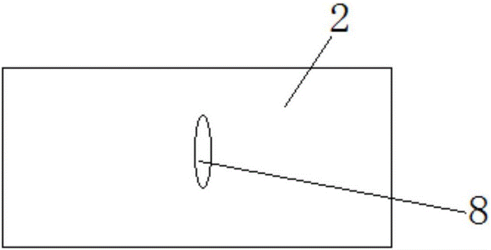
[0003] Since the substrate 2 needs to be placed on the drying platform 3 for processing, the photoresist on the substrate 2 has a certain fluidity, and the bending (bending) of the substrate 2 will cause the solvent to flow to the middle, and the solvent in the middle is more than the surrounding , the thickness of the formed intermediate photoresist film is thicker than the thickness of the photoresist film around the substrate; at the same time, when the substrate is vacuum-dried on the drying platform, the exhaust pipe is exhausted from the surrounding to the surrounding. When exhausting, because the exhaust hole is discharged from the bottom, this will cause the periphery of the substrate to dry easily, and the drying speed in the middle of the substrate will be slower, which will affect the overall Dry Mura (drying uniformity) of the substrate. , it is easy to produce as image 3 Dry Mura defect shown 8
The existing methods are dealing with new processes such as half tone (semi-transparent exposure process), which can reduce the number of masks, and the takt time will become longer and longer. If an additional Pump is added, the cost will increase accordingly

Method used


Image

  • Pressure-reduction drying system and method for substrate
  • Pressure-reduction drying system and method for substrate
  • Pressure-reduction drying system and method for substrate

Examples


Embodiment Construction

[0028] The technical solutions of the present invention will be clearly and completely described below in conjunction with the accompanying drawings. Apparently, the described embodiments are some of the embodiments of the present invention, but not all of them. Based on the embodiments of the present invention, all other embodiments obtained by persons of ordinary skill in the art without making creative efforts belong to the protection scope of the present invention.

[0029] In the description of the present invention, it should be noted that unless otherwise specified and limited, the terms "installation", "connection" and "connection" should be understood in a broad sense, for example, it can be a fixed connection or a detachable connection. Connected, or integrally connected; it may be mechanically connected or electrically connected; it may be directly connected or indirectly connected through an intermediary, and it may be the internal communication of two components. ...


PUM


Abstract

The invention discloses a pressure-reduction drying system and method for a substrate. The pressure-reduction drying system comprises an airtight drying cavity (1). A drying platform (3) used for bearing the substrate (2) is arranged in the drying cavity (1). Vacuumizing holes (4) communicating with the interior of the drying cavity are further formed in the drying cavity (1). The pressure-reduction drying system is provided with a temperature controller (5). A heating structure (6) used for heating the substrate (2) is arranged on the drying platform (3). The temperature controller (5) is electrically connected with the heating structure (6) and used for controlling the heating temperature of the heating structure (6). According to the pressure-reduction drying system and method for the substrate, the heating structure is arranged on the drying platform for bearing the substrate, the heating temperature of the heating structure is controlled through the temperature controller, and time for removing a solvent of the substrate in the drying cavity is shortened under the dual effects of vacuumizing and heating, the drying efficiency is improved, and the productivity is improved accordingly.

Description

technical field [0001] The invention relates to the technical field of substrate drying, in particular to a substrate decompression drying system and a drying method thereof. Background technique [0002] At present, in the yellow light process of FPD (Flat Panel Display) factory, an important unit is decompression drying. The main principle is to remove the solvent from the coated photoresist by vacuuming to achieve the initial curing effect. ,Such as figure 1 structure shown. At present, a dry pump (vacuum pump) is mainly used to pump air to ensure the negative pressure in the drying chamber 1 so as to discharge the solvent of the photoresist on the substrate 2 . In the Chamber (chamber) of the substrate 1, a certain degree of vacuum is achieved through the lower two exhaust holes to ensure the process. [0003] Since the substrate 2 needs to be placed on the drying platform 3 for processing, the photoresist on the substrate 2 has a certain fluidity, and the bending (be...

Claims


Application Information

Patent Timeline
Patent Type & Authority Applications(China)
IPC IPC(8): B05D3/02B05D3/04
CPCB05D3/0254B05D3/0493
Inventor 费国东
Owner KUNSHAN GO VISIONOX OPTO ELECTRONICS CO LTD
Learn More