
Puncture wire clamp

A technology for piercing wire clamps and clips, which is applied in the direction of clamping/spring connection, needle point/slotted plate contact parts and electrical components used to penetrate insulated wires/cable core wires, and can solve the problem that it is difficult to ensure the contact between the tooth piece and the Power cables are in close contact, anti-corrosion aging, poor firmness and other issues, to achieve the effect of improved sealing, strong current carrying capacity, and balanced grip

Active Publication Date: 2016-11-09
阮浩新 +1
View PDF6 Cites 3 Cited by
  • Summary
  • Abstract
  • Description
  • Claims
  • Application Information

AI Technical Summary

Problems solved by technology

In the traditional puncture clamp, only the upper shell part of the tooth piece can adjust the tooth piece angle with the deformation of the shell. When using power cables with different diameters, it is difficult to ensure the close contact between the tooth piece and the power cable, as well as uniform grip and firmness. Poor, easy to loosen; and the shell adopts upper and lower opening and closing methods for gap connection, resulting in large gaps and gaps in the shell structure, which affects the performance of fire protection, waterproof, and anti-corrosion aging

Method used


Image

  • Puncture wire clamp
  • Puncture wire clamp
  • Puncture wire clamp

Examples


Embodiment Construction

[0030] In order to make the purpose, technical solution and advantages of the present invention more clear, the following will give descriptions of specific embodiments in conjunction with the accompanying drawings of the present invention, but not as any limitation to the present invention.

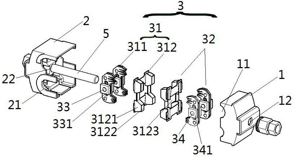
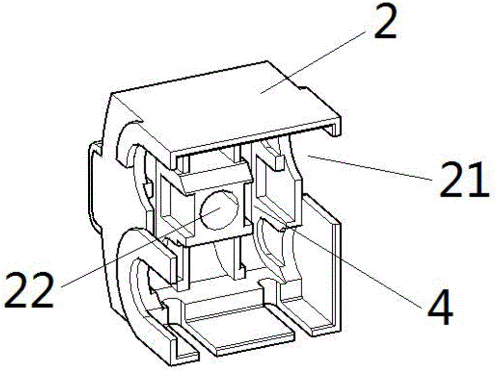
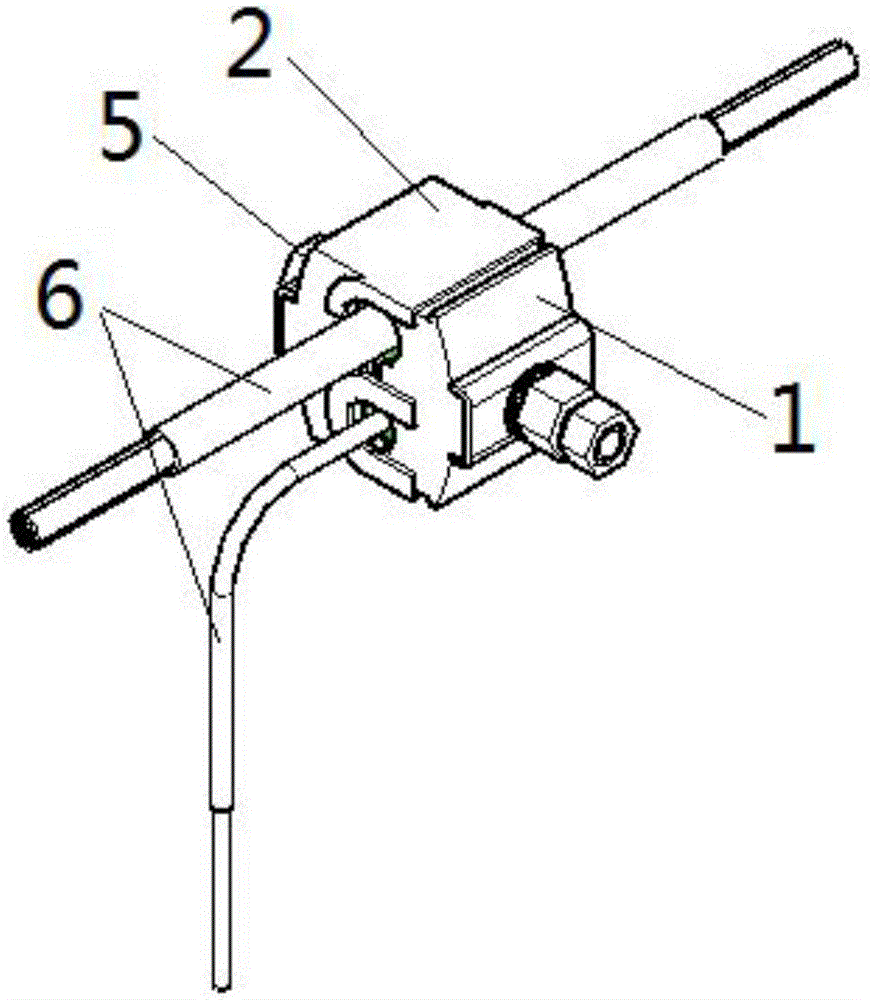
[0031] see figure 1 and figure 2 , a puncture wire clamp, including a front cover 1, a rear cover 2 and a plurality of clamping units 3; the front cover 1 and the rear cover 2 are detachably and fixedly connected, and the side of the front cover 1 facing the rear cover 2 is provided with a first opening Slot 11, the side of the back cover 2 facing the front cover 1 is provided with a second opening slot 21 opposite to the opening of the first opening slot 11, the first opening slot 11 and the second opening slot 21 are buckled to form a clamping power cable Inclusion hole; each clamping unit 3 includes a first clamping part 31 and a second clamping part 32, the first clamping part 31 i...


PUM


Abstract

The invention relates to a puncture wire clamp. The puncture wire clamp comprises a front cover, a rear cover and a plurality of clamping units. The front cover and the rear cover are detachably and fixedly connected. A first open groove is formed on one side, facing the rear cover, of the front cover. A second open groove opposite to the first open groove is formed on one side, facing the front cover, of the rear cover. The first open groove and the second open groove are engaged to form a clathration hole for clamping a power cable. Each clamping unit comprises a first clamping part and a second clamping part. The first clamping part is fixed in the front cover through a first connection shaft. The second clamping part is fixed in the rear cover through a second connection shaft. The puncture wire clamp has the advantages that the first clamping part and the second clamping part are capable of respectively and automatically adjusting angles through the first connection shaft and the second connection shaft so as to be adapted to the dynamic deformation of the first clamping part and the second clamping part under external forces when the power cables of different outer diameters penetrate, so that the tight contact of the first clamping part and the second clamping part with the power cable is realized, and the puncture gripping power is balanced and consistent.

Description

technical field [0001] The invention relates to the technical field of electric power fittings for overhead lines, in particular to a piercing clip, in particular to a novel piercing clip with adjustable center compensation. Background technique [0002] In the construction of overhead power lines, when the cables need to be branched or spliced, it is necessary to use splicing clamps to connect two insulated power cables together. The connection clamp, especially the piercing type connection clamp, has the characteristics of easy installation, low cost, safety, reliability and maintenance-free. In the traditional puncture clamp, only the upper shell part of the tooth piece can adjust the tooth piece angle with the deformation of the shell. When using power cables with different diameters, it is difficult to ensure the close contact between the tooth piece and the power cable, as well as uniform grip and firmness. It is poor and easy to loosen; and the shell is connected by ...

Claims


Application Information

Patent Timeline
IPC IPC(8): H01R11/07H01R4/24H01R4/44
CPCH01R4/2408H01R4/44H01R11/07
Inventor 阮浩新肖雄
Owner 阮浩新
Learn More