A separate heat pipe evaporator heated by rotating flow

A separate heat pipe and swirling flow technology, applied in evaporators/condensers, indirect heat exchangers, heat exchanger shells, etc., can solve the problems of large liquid filling, large space occupation, and low heat transfer performance. Achieve the effects of improved pressure bearing capacity, concentrated and uniform return liquid, and compact structural design

Active Publication Date: 2021-07-09
CHINA ACAD OF AEROSPACE AERODYNAMICS
View PDF7 Cites 0 Cited by
  • Summary
  • Abstract
  • Description
  • Claims
  • Application Information

AI Technical Summary

Problems solved by technology

The deficiencies of these mentioned separated heat pipe heat exchangers are summarized as follows: (1) The evaporator is bulky; (2) The welding and assembly of components are inconvenient; (3) There are many welds, irregular positions, and leakage of working fluid. The possibility is greatly increased; (4) the structural design is extremely unsuitable for the small space; (5) the space at the bottom of the evaporator is too large, that is, a large amount of liquid needs to be filled; (5) the steam pipe and the liquid pipe are changed from The side leads and leads of the heater take up more space; (6) Zigzag-shaped fluid baffle structure is adopted, the layout of baffles and tubes is complex and cumbersome, and the corner fluid stagnation area increases, and the heat transfer performance is not good. high etc.

Method used


Image

  • A separate heat pipe evaporator heated by rotating flow
  • A separate heat pipe evaporator heated by rotating flow
  • A separate heat pipe evaporator heated by rotating flow

Examples


Embodiment Construction

[0040] The present invention will be further described in detail below in conjunction with the accompanying drawings and specific embodiments.

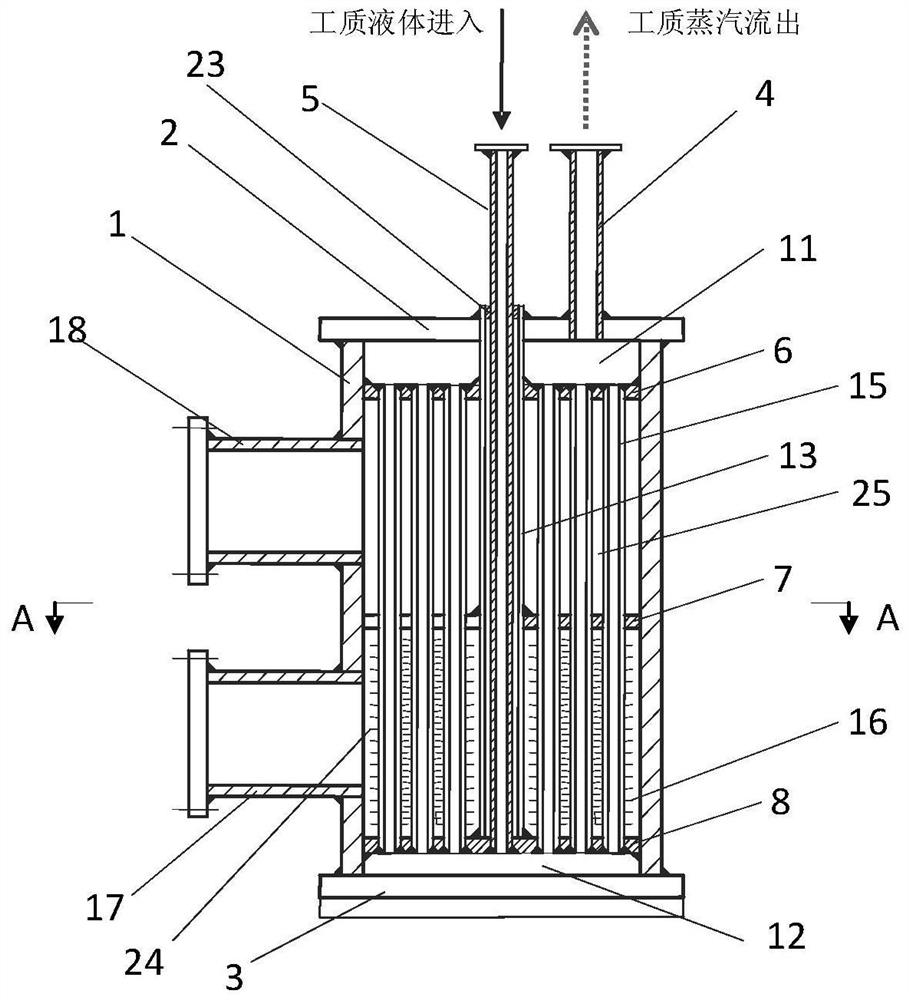
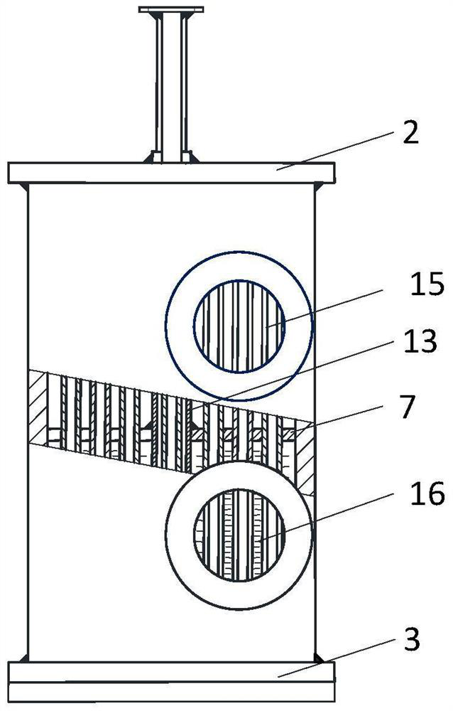
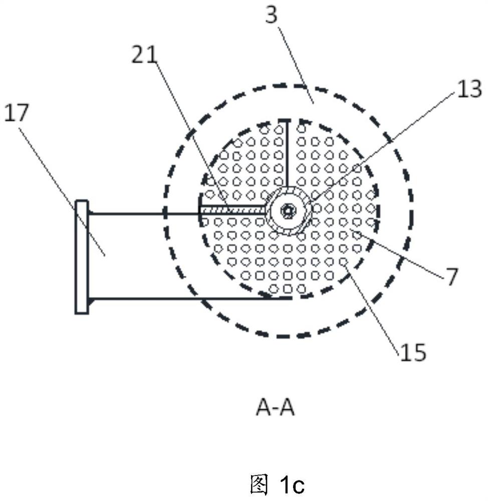
[0041] Such as figure 1 Shown are the three side views of the separated heat pipe evaporator heated by the swirling flow of the present invention, wherein Figure 1a main view, Figure 1b for the side view, figure 1 c is a top view. figure 1 The structural design of the evaporator with a cylindrical shell is given, and the cylindrical evaporator is taken as an example to describe in detail below. Depend on figure 1 It can be seen that the evaporator of the present invention includes a shell 1, an upper end cover 2, a lower end cover 3, a steam outlet pipe 4; a liquid pipe 5, an upper partition 6, n middle partitions 7 of heat exchange fluids, a lower partition 8, a steam chamber 11, Liquid chamber 12, isolation pipe 13, evaporation pipe 15, fins 16, heat exchange fluid inlet pipe 17, heat exchange fluid outlet pipe 18, heat excha...


PUM


Abstract

The invention relates to a separated heat pipe evaporator heated by rotating flow. Two or more heat exchange fluid passages are formed by using partition plates in the heat exchange fluid. Circumferential circulation in each zone, the circumferential circulation of different channels passes through the openings on the baffles in the heat exchange fluid for axial flow connection, the fluid flow has no dead zone retention, and completely eliminates the baffles when the traditional Zigzag baffle structure is used for flow. The stagnation of the corner area makes the heat exchange sufficient and the resistance smaller; the liquid pipe and the steam outlet pipe are arranged on the top of the shell, and the liquid pipe passes through the shell to communicate with the liquid chamber at the bottom, and the outer wall of the liquid pipe is set with an isolation pipe. The structural design makes the central liquid inlet pipe pass through the central isolation pipe without being heated, and the return liquid will not be heated to generate steam to block the liquid return flow, and the return liquid of the present invention is more concentrated and uniform, and the filling volume of the working medium is greatly reduced , The structure of the evaporator is more compact and miniaturized.

Description

technical field [0001] The invention belongs to the technical field of separated heat pipes in engineering thermophysics and heat pipe disciplines, and relates to a novel structural design of a separated heat pipe evaporator, in particular to a separated heat pipe evaporator heated by swirling flow. Background technique [0002] The heat pipe is a high-performance heat transfer element, which is a device that continuously transfers heat from the heat source to the heat sink by the evaporation, condensation and reflow of the internal working medium (working fluid). Heat pipes are used in a wide range of applications. With the development of technology, the demand for heat pipes continues to grow. [0003] The structure of the heat pipe is various, and the split heat pipe is a kind of heat pipe. Separate Type Heat Pipe (STHP) is generally composed of evaporator, condenser, steam pipe and liquid pipe. Vaporizer design is a key to achieving the desired performance of split hea...

Claims


Application Information

Patent Timeline
Patent Type & Authority Patents(China)
IPC IPC(8): F28D15/02F25B39/02F28F9/00
CPCF25B39/022F28D15/02F28F9/00
Inventor 曲伟薛志虎艾邦成
Owner CHINA ACAD OF AEROSPACE AERODYNAMICS
Why Eureka
Try Eureka