Mill stand for rolling rod-like or tubular rolling stock

A technology for rolling mill racks and rolled pieces, which is applied to metal rolling racks, metal rolling mill stands, metal rolling, etc., and can solve problems such as excessive installation and adjustment time

Inactive Publication Date: 2010-05-05
KOCKS TECH GMBH & CO
View PDF3 Cites 0 Cited by
  • Summary
  • Abstract
  • Description
  • Claims
  • Application Information

AI Technical Summary

Problems solved by technology

However, this positioning of the rolls results in a long set-up time when it is required to replace a roll with an additional roll in such a roll stand

Method used


Image

  • Mill stand for rolling rod-like or tubular rolling stock
  • Mill stand for rolling rod-like or tubular rolling stock

Examples


Embodiment Construction

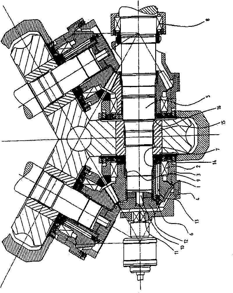
[0020] As can be seen from the drawing, the bevel gear 1 is supported in the eccentric bushing 3 by means of a rolling bearing 2, and the bevel gear rotates the eccentric bushing 3 each time via the trapezoidal thread 4 arranged on the outside on the eccentric bushing 3 in a known manner. Cover 3 when just moved axially. Accordingly, the bevel gear moves axially on the roll shaft 5 , which is supported radially in the bevel gear via sleeves 6 , 7 and is held fixed in its axial position by an axial bearing 8 . The torque is positively transmitted from the roll shaft 5 to the bevel gear via the involute toothing 9 . The tension rod force F is transmitted from the tension rod 10 via the thread 11 to the cover 12 and from there as pressure via a plurality of pressure screws 13 spaced at equal intervals on the circumference to the compression ring 14 . The compression ring 14 transmits the tension force to the roll hub 15 and thus presses the roll hub against the shaft shoulder 1...


PUM


Abstract

The invention discloses a mill housing for bar or tubular rolled piece, comprising at least one axis supporting the roller, said roller is installed on said axis movably in axial direction, the two sides of roller is equipped with a location device in axial direction, and a bushing is installed on said axis. The location device is formed by at least one movable location element extending through bushing from side far away from roller to side facing roller in axial direction; the place far away from roller in bushing is bounded by a backstop element installed on side far away from roller; and said backstop element is adjustable in axial direction and fixed connected with axis. s

Description

technical field [0001] The invention relates to a rolling mill stand for rolling rod-shaped or tubular products such as wire or tube. Background technique [0002] The rod-shaped or tubular rolling stock is formed by rolling in a rolling mill with a rolling stand, wherein a plurality of rolls arranged in a plane and forming a central pass opening are arranged in the rolling stand. Generally, three or four rolls are arranged such that they form the said central pass opening relative to each other. In such rolling stands, known constructions have only a single rotary drive. Thus, the bevel gears arranged on this shaft that mesh with the bevel gears arranged on adjacent shafts transmit the torque of this one transmission shaft to those shafts supporting the other rolls. For example EP1449597A2 has just shown the structural scheme of a kind of such rolling stand. [0003] As also described in EP 1 449 597 A2, such rolling stands usually have adjustment options for the pass op...

Claims


Application Information

Patent Timeline
Patent Type & Authority Patents(China)
IPC IPC(8): B21B31/02B21B31/22B21B31/26B21B13/10
CPCB21B31/26B21B27/035B21B13/103B21B31/08
Inventor H·波特霍夫
Owner KOCKS TECH GMBH & CO
Why Eureka
Try Eureka