
Dry quenching waste heat recovery steam generator turbine steam admission/emission control method

A waste heat recovery and steam turbine technology, applied in engine components, machines/engines, mechanical equipment, etc., can solve problems such as large fluctuations in steam pressure, no consideration of steam turbine inlet and exhaust pressure, and stability interference of steam turbine power generation, so as to ensure stability. running effect

Active Publication Date: 2016-11-09
鞍钢集团工程技术有限公司
View PDF5 Cites 9 Cited by
  • Summary
  • Abstract
  • Description
  • Claims
  • Application Information

AI Technical Summary

Problems solved by technology

[0005] In the existing steam turbine speed regulation system, most of them only collect the speed of the steam turbine as the system feedback value, measure the displacement of the output end of the oil motor through the displacement sensor and compare it with the opening of the main steam valve, without considering the steam inlet and exhaust pressure of the steam turbine, However, since the coke CDQ waste heat recovery power generation system is a small power generation unit, and the waste heat power resource has the characteristics of large fluctuations in steam pressure, the steam pressure has caused great interference to the stability of steam turbine power generation.

Method used


Image

  • Dry quenching waste heat recovery steam generator turbine steam admission/emission control method
  • Dry quenching waste heat recovery steam generator turbine steam admission/emission control method
  • Dry quenching waste heat recovery steam generator turbine steam admission/emission control method

Examples


Embodiment Construction

[0023] The specific embodiment of the present invention will be further described below in conjunction with accompanying drawing:

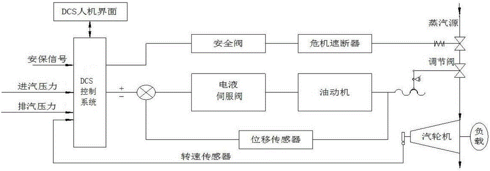
[0024] Such as figure 1 As shown, the CDQ waste heat recovery steam turbine inlet and exhaust steam control method of the present invention is characterized in that it comprises the following steps:

[0025] 1) The speed sensor collects the speed signal of the main shaft of the steam turbine, and transmits the speed signal to the DCS control system, and displays it as the monitoring value of the speed of the steam turbine;

[0026] 2) if figure 2 As shown, the present invention carries out PID cascade adjustment to the inlet steam pressure of the steam turbine through the DCS control system; a double-loop control system is adopted, the main loop is the steam inlet steam pressure, and the secondary loop is the steam inlet steam flow; the specific process is:

[0027] The main loop compares the set value of the inlet steam pressure with the measu...


PUM


Abstract

The invention relates to a dry quenching waste heat recovery steam generator turbine steam admission / emission control method. The method comprises the following steps: a speed sensor acquires a steam turbine spindle speed signal and performs display as a steam turbine speed monitoring value; PID (proportional-integral-derivative) cascade control is carried out on the steam turbine steam admission / emission pressure by using a DCS (distributed control system); a double-loop control system is adopted, wherein the primary loop is steam admission / emission pressure, and the auxiliary loop is steam admission / emission flow rate; the DCS outputs a current control signal, so that the main steam valve and steam emission regulating valve reach the corresponding opening; and the output of an electrohydraulic servo valve is regulated by a displacement sensor so as to control the actual speed of the steam turbine to be consistent with the target speed. On the basis of the conventional turbine control system, the steam turbine steam admission / emission pressure is respectively subjected to PID cascade control by using the DCS, so that the turbine steam admission pressure and steam emission pressure are kept stable, and the disturbance on the steam turbine is reduced when the load is increased or decreased, thereby ensuring the stable operation of the steam turbine.

Description

technical field [0001] The invention relates to the technical field of steam power generation, in particular to a method for controlling the intake and exhaust steam of a steam turbine for coke dry quenching waste heat recovery. Background technique [0002] The steam turbine is the prime mover of the power plant, which drives the synchronous generator to rotate to generate electric energy, and transmits electric power that meets the requirements of quantity and power supply quality (voltage and frequency) to the grid. Known from the operating characteristics of the synchronous generator, the terminal voltage of the generator is determined by the reactive power, and the reactive power is determined by the excitation of the generator; the frequency (or cycle) of the grid is determined by the active power, that is, by the prime mover drive power. Therefore, the voltage regulation of the grid belongs to the excitation system of the generator, and the frequency regulation belon...

Claims


Application Information

Patent Timeline
IPC IPC(8): F01D17/08F01D15/10
CPCF01D15/10F01D17/08
Inventor 赵楠赵建东
Owner 鞍钢集团工程技术有限公司
Learn More