Deoiling and scumming device for sewage treatment plant
A technology for sewage treatment plants and sewage treatment tanks, which is applied in water/sludge/sewage treatment, grease/oil/float removal devices, water pollutants, etc. Eliminate problems such as complicated methods to achieve the effect of easy removal and lower removal costs
- Summary
- Abstract
- Description
- Claims
- Application Information
AI Technical Summary
Problems solved by technology
Method used
Image

Examples
Embodiment 1
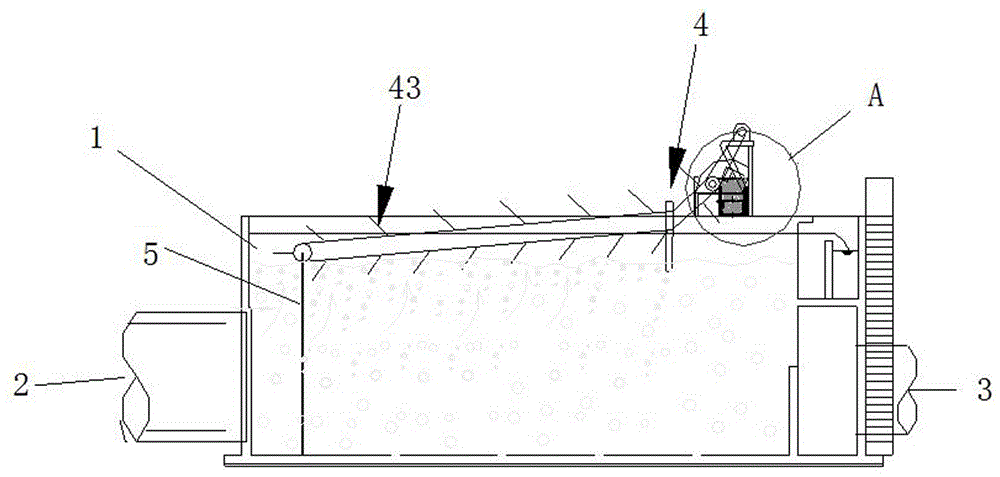
[0032] refer to figure 1 , in the open sewage treatment tank, one end of the sewage treatment tank is provided with a sewage inlet, and the other end is provided with a water outlet; the top of the sewage treatment tank is provided with an oil scraping system, and the oil scraping system is composed of a transmission bracket and a transmission bracket The connected oil scraping combs are connected; the sewage inlet is equipped with a deflector, one end of the deflector is the automatic end, and the other end is connected to one side of the transmission bracket. The setting of the deflector can make it enter the sewage treatment The sewage in the pool is turned from bottom to top, which is conducive to the oil in the sewage being pushed up to the water surface, so that the subsequent degreasing work can be carried out smoothly.
[0033] Preferably, the transmission device includes a transmission roller and a belt matched with the transmission roller, the belt is provided with a...
Embodiment 2
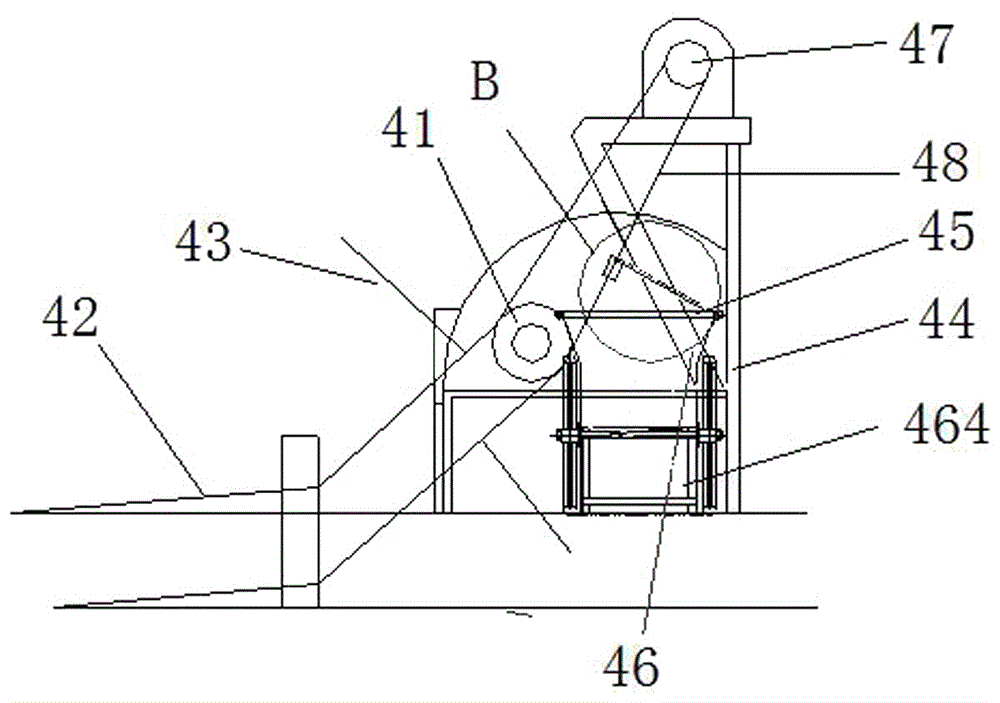
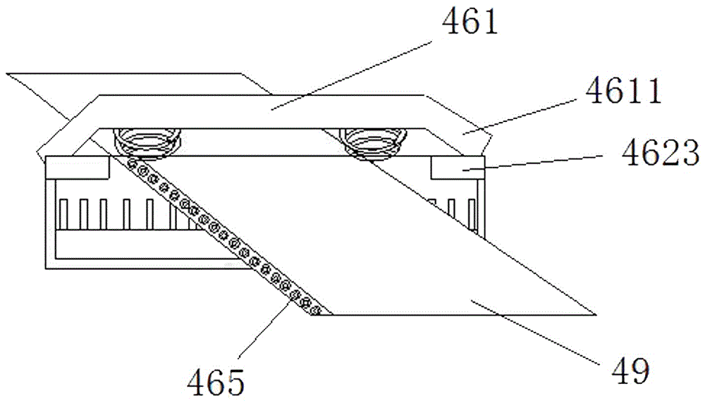
[0035] refer to image 3 and Figure 4 It is a schematic diagram of the specific structure and a schematic diagram of the dispersed structure of the oil scraping device. The oil scraping device described here is connected by an upper elastic extrusion part and a lower comb structure, and a set of springs is arranged below the elastic extrusion part.
[0036] At the same time, there is an oil collecting tank under the oil scraping device. There is an angle of 5 degrees between the fixed bracket and the oil scraping platform, which is conducive to the scraping and falling of grease. One side of the fixed bracket frame is wrapped with an oil-absorbing blanket, and the other side is equipped Oil scraping roller; the comb tooth structure is composed of a comb tooth bar on the bottom plate. hole.
[0037] Further, the oil scraping device and the support frame are rotatably connected, and limit stops are provided on both sides of the bottom plate, and a downward pressure limit bar ...
Embodiment 3
[0040] see figure 1 Among them, an angle of 50 degrees is formed between the fixed bracket and the belt, so that the oil-absorbing felt can be used to absorb oil to the maximum extent, and the oil-absorbing area is expanded at the same time. There are two driving rollers, and the height difference between the two driving rollers is two 1 / 5 of the linear distance between the rollers, the slow lifting here is conducive to the adsorption of grease and the firmness after adsorption.
[0041] Furthermore, a belt bracket is provided between the two driving rollers, and the belt is divided into a first belt working platform and a second belt working platform after being divided by the belt bracket, and the angle between the first belt working platform and the horizontal plane is 3 -10 degrees, the angle between the second belt working platform and the horizontal plane is 40-60 degrees. Setting two different angles here is also to ensure the strength and effect of grease adsorption ...
PUM
 Abstract
Description
Claims
Application Information
 - R&D
- Intellectual Property
- Life Sciences
- Materials
- Tech Scout
- Unparalleled Data Quality
- Higher Quality Content
- 60% Fewer Hallucinations
Browse by: Latest US Patents, China's latest patents, Technical Efficacy Thesaurus, Application Domain, Technology Topic, Popular Technical Reports.
© 2025 PatSnap. All rights reserved.Legal|Privacy policy|Modern Slavery Act Transparency Statement|Sitemap|About US| Contact US: help@patsnap.com