
Feeding disc for small hardware

A technology for small hardware parts and feeding trays is applied in the field of hardware parts preparation to achieve the effects of high feeding accuracy, fast processing, and improved effective speed.

Active Publication Date: 2016-11-09
PINGHU PINYAO MACHINERY AUTOMATION CO LTD
View PDF4 Cites 0 Cited by
  • Summary
  • Abstract
  • Description
  • Claims
  • Application Information

AI Technical Summary

Problems solved by technology

[0007] The purpose of the present invention is to solve the current feeding problem of special small hardware, and provide a feeding tray for small hardware, which can feed the raw materials of small hardware to the processing equipment in a certain direction, so as to meet the requirements of Requirements for the sequence of raw materials in subsequent processing

Method used


Image

  • Feeding disc for small hardware
  • Feeding disc for small hardware
  • Feeding disc for small hardware

Examples


Embodiment

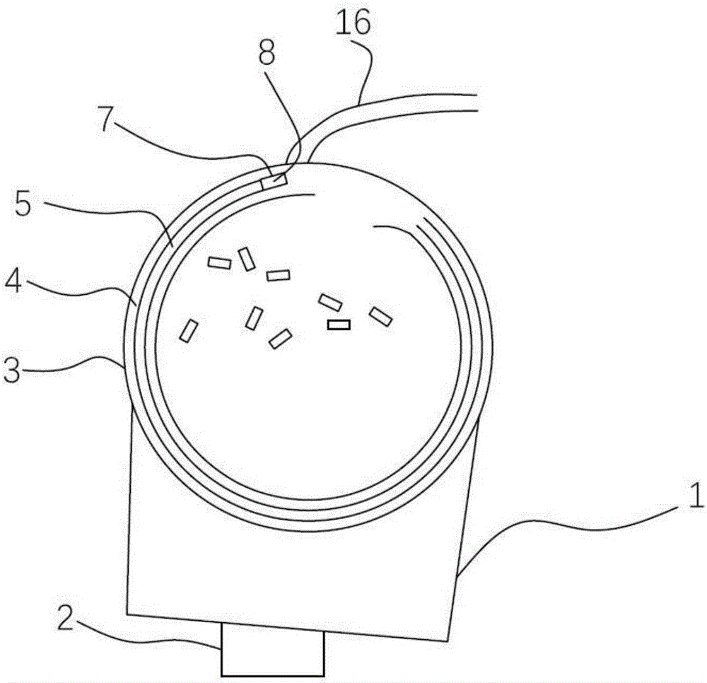
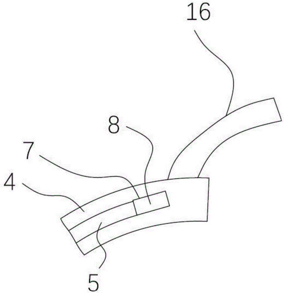
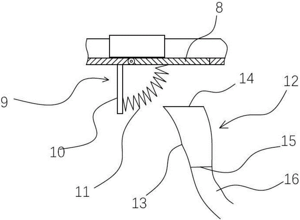
[0029] A feeding tray for small hardware, such as figure 1 As shown, it includes a base 1 on which a vibrator 2 is set, a feeding hopper 3 is arranged on the base 1, and a spirally rising feeding channel 4 is arranged on the inner wall of the feeding hopper 3, and a feeding channel 5 is provided on the feeding channel 4 along its rising direction, and the feeding channel 5 is Arc-shaped groove, the width of feeding groove 5 matches the width of small hardware, such as Figure 4 , 5 , 6, the bottom of the feeding trough 5 is provided with some parallel stripes 6, as Figure 4 As shown, the stripes 6 are arranged laterally along the rising feeding chute 5, as Figure 5 As shown, the stripes 6 are longitudinally arranged along the rising feeding trough 5; as Figure 6 shown in Figure 4 On the basis of , divide several stripes 6 into one group, and arrange them at intervals in the form of groups. In order to reduce friction, (not marked in the figure), the bottom of the feed...


PUM


Abstract

The invention relates to the technical field of hardware preparation, in particular to a feeding disc for small hardware. The feeding disc comprises a base with a vibrator, wherein a feeding hopper is arranged on the base; a spiral feeding channel is arranged on the inner wall of the feeding hopper; a feeding groove is formed in the feeding channel in the spiral direction of the feeding channel; the feeding groove is an arc-shaped groove; the width of the feeding groove is matched with that of the small hard ware; and a plurality of strip-shaped patterns arranged side by side are arranged at the bottom of the feeding groove. The feeding disc can continuously, uniformly and quickly feed the hardware into a feeding pipe at a preset angle, the hardware is fed into the feeding pipe at short intervals, and the feeding accuracy is high, so that the effective speed is increased, and the requirement of quick processing can be met.

Description

technical field [0001] The invention relates to the technical field of hardware preparation, in particular to a feeding tray for small hardware. Background technique [0002] With the popularization of automation and semi-automation in various industries of the economy, automatic feeding devices have become an indispensable link in the production line. [0003] The automatic feeding vibrating plate is a kind of feeding equipment with automatic orientation and sorting. Its working purpose is to automatically and orderly arrange the disordered workpieces neatly and accurately through vibration to transport them to the next process. The vibrating plate is an auxiliary equipment for automatic assembly machinery, which can discharge various products in an orderly manner. It can cooperate with automatic assembly equipment to assemble various parts of the product into a complete product. [0004] The automatic feeding vibrating plate is mainly composed of hopper, chassis, control...

Claims


Application Information

Patent Timeline
Patent Type & Authority Applications(China)
IPC IPC(8): B65G27/02B65G47/14B23Q7/18
CPCB23Q7/18B65G27/02B65G47/1421B65G2201/0214
Inventor 黄春平
Owner PINGHU PINYAO MACHINERY AUTOMATION CO LTD
Learn More