A profile cutting machine capable of deburring

A deburring mechanism and deburring technology, applied in the direction of machine tools suitable for grinding workpiece edges, machine tools suitable for grinding workpiece planes, and parts of grinding machine tools, which can solve the problem of affecting the cutting effect and prone to deflection , low efficiency and other issues, to achieve the effect of ensuring removal effect, avoiding profile deformation and accurate positioning

Active Publication Date: 2018-06-22
浙江东方大港大河工程塑料有限公司
View PDF5 Cites 2 Cited by
  • Summary
  • Abstract
  • Description
  • Claims
  • Application Information

AI Technical Summary

Problems solved by technology

[0002] At present, plastic doors and windows are commonly used window structures in buildings. Plastic doors and windows usually consist of profiles such as stiles and layering bars. Profile cutting machines are suitable for sawing various special-shaped metals such as aluminum, aluminum alloys, copper, copper alloys, non-metallic plastics, and carbon fibers. It is especially suitable for sawing aluminum doors and windows, photo frames, plastic steel materials, bakelite boards, aluminum extrusions, paper tubes and profiles. Traditionally used profile cutting machines have problems such as insufficient positioning of profiles and unstable positioning. It is prone to deflection and other situations, which will affect the cutting effect. Traditionally applied profiles will leave burrs on the cutting end face of the tool, which will affect the quality of further processing. These burrs must be removed before painting or finishing the profile.
Relying on manual use of brushes to repeatedly rub and deburr the end surface of the profile, the labor intensity is high and the efficiency is low, so it is necessary to propose a profile cutting machine that can deburr

Method used


Image

  • A profile cutting machine capable of deburring
  • A profile cutting machine capable of deburring
  • A profile cutting machine capable of deburring

Examples


Embodiment Construction

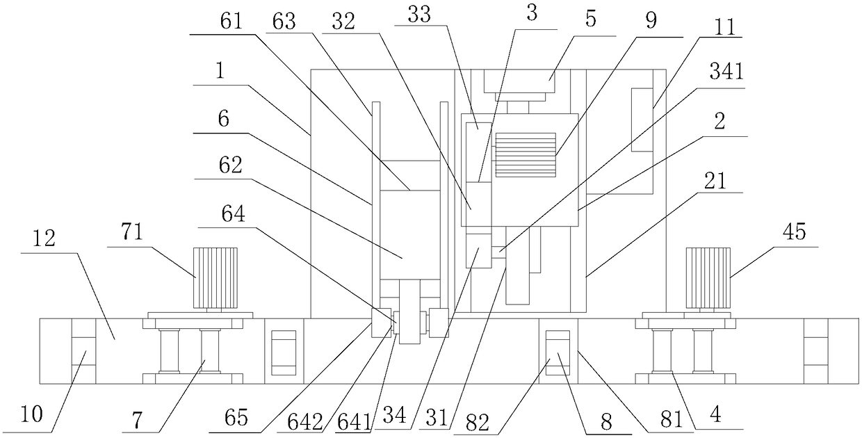
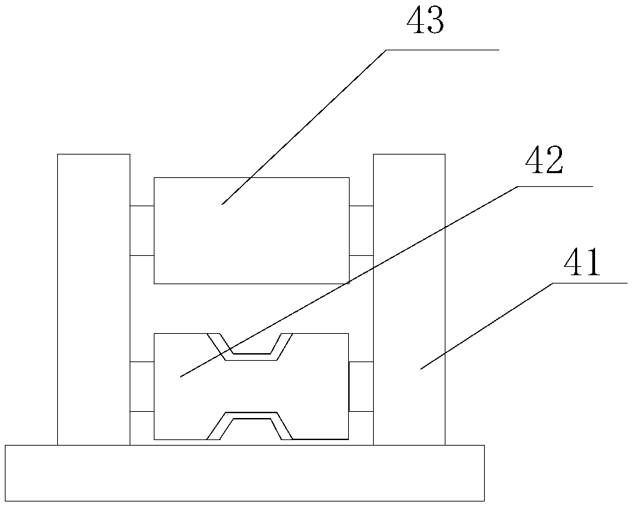
[0021] refer to figure 1 , figure 2 , image 3 , Figure 4 , Figure 5 and Figure 6 , a profile cutting machine capable of deburring according to the present invention, comprising a workbench 1, a sliding seat 2, a cutting device 3, a first conveying device 4, a driving hydraulic cylinder 5, a deburring device 6, a second conveying device 7, a clamping device 8 and motor 9, the workbench 1 is provided with a sliding seat 2, and the sliding seat 2 moves horizontally along the slide rail 21 under the drive of the driving hydraulic cylinder 5, and the sliding seat 2 is provided with a cutting device 3, Described cutting device 3 is provided with emery wheel 31, and described emery wheel 31 rotates under the drive of motor 9, and the left side of described cutting device 3 is provided with deburring device 6, and described deburring device 6 is provided with slide table 62 , several deburring mechanisms 65 are installed on the slide table 62, a transfer table 12 is provided...


PUM


Abstract

The invention provides a profile cutting machine capable of deburring. The profile cutting machine comprises a workbench, a sliding seat, a cutting device, a first conveying device, a hydraulic driving cylinder, a deburring device, a second conveying device, a clamping device and a motor, wherein the workbench is provided with the sliding seat which horizontally moves along a sliding rail under the drive of the hydraulic driving cylinder; the sliding seat is provided with the cutting device on which a grinding wheel is arranged; the grinding wheel rotates under the drive of the motor; the left side of the cutting device is provided with the deburring device on which a sliding table is arranged; a plurality of deburring mechanisms are mounted on the sliding table; a conveying platform is provided with the first conveying device and the second conveying device; the clamping device is matched with the first conveying device and the second conveying device; and a control system is connected with the hydraulic driving cylinder and the motor. The profile cutting machine is accurate in location and capable of avoiding the phenomenon such as deflection caused in a profile cutting process and deburring end surfaces of cut profiles.

Description

【Technical field】 [0001] The invention relates to the technical field of profile processing equipment, in particular to a profile cutting machine capable of deburring. 【Background technique】 [0002] At present, plastic doors and windows are commonly used window structures in buildings. Plastic doors and windows are usually composed of profiles such as stiles and layering bars. Profile cutting machines are suitable for sawing various special-shaped metals such as aluminum, aluminum alloys, copper, copper alloys, non-metallic plastics, and carbon fibers. It is especially suitable for sawing aluminum doors and windows, photo frames, plastic steel materials, bakelite boards, aluminum extrusions, paper tubes and profiles. Traditionally used profile cutting machines have problems such as insufficient positioning of profiles and unstable positioning. It is prone to deflection and other situations, which will affect the cutting effect. Traditionally applied profiles will leave burr...

Claims


Application Information

Patent Timeline
Patent Type & Authority Patents(China)
IPC IPC(8): B24B27/06B24B41/06B24B9/20B24B41/00B24B55/00B24B7/16B24B27/00B24B47/08
CPCB24B7/16B24B9/20B24B27/0076B24B27/06B24B41/005B24B41/06B24B47/08B24B55/00
Inventor 徐向荣李德宏顾建标
Owner 浙江东方大港大河工程塑料有限公司
Why Eureka
Try Eureka