
Inlaying structure for telecommunication base station filter cavity mold and production method thereof

A cavity mold and communication base station technology, applied in the field of die casting production, can solve the problems of high cost and long mold investment cycle, and achieve the effect of saving production cost, reducing grinding workload and improving surface quality

Active Publication Date: 2016-11-09
ZHUHAI RUNXINGTAI ELECTRICAL +1
View PDF8 Cites 4 Cited by
  • Summary
  • Abstract
  • Description
  • Claims
  • Application Information

AI Technical Summary

Problems solved by technology

[0003] In order to solve the problem of long mold investment cycle and high cost when product modification and upgrading, the invention provides a mosaic structure and production method for filter cavity molds for communication base stations

Method used


Image

  • Inlaying structure for telecommunication base station filter cavity mold and production method thereof
  • Inlaying structure for telecommunication base station filter cavity mold and production method thereof
  • Inlaying structure for telecommunication base station filter cavity mold and production method thereof

Examples


Embodiment Construction

[0029] In order to make the purpose, technical solutions and advantages of the embodiments of the present invention clearer, the technical solutions in the embodiments of the present invention will be clearly and completely described below in conjunction with the drawings in the embodiments of the present invention. Obviously, the described embodiments It is a part of embodiments of the present invention, but not all embodiments. Based on the embodiments of the present invention, all other embodiments obtained by persons of ordinary skill in the art without making creative efforts belong to the protection scope of the present invention. It should be noted that, in the case of no conflict, the embodiments in the present application and the features in the embodiments can be combined arbitrarily with each other.

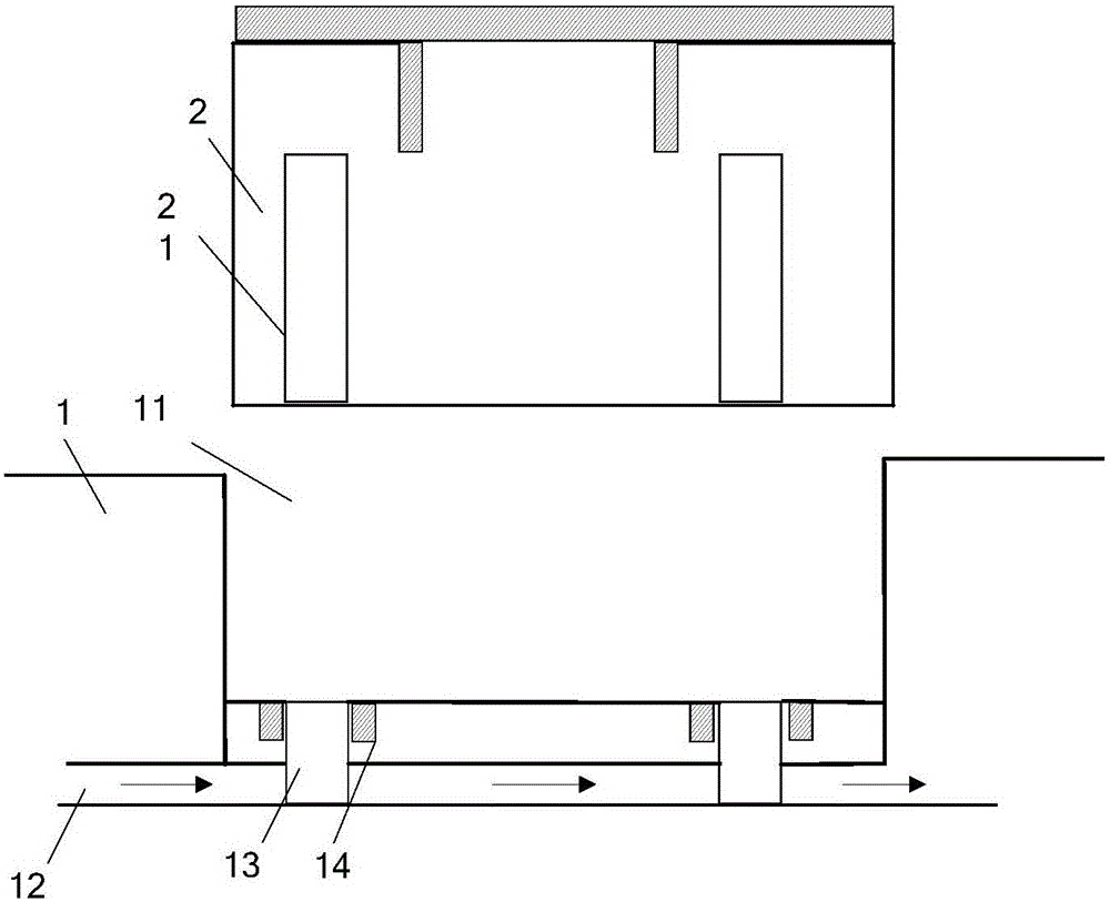
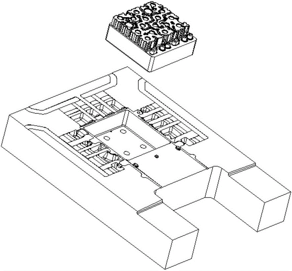
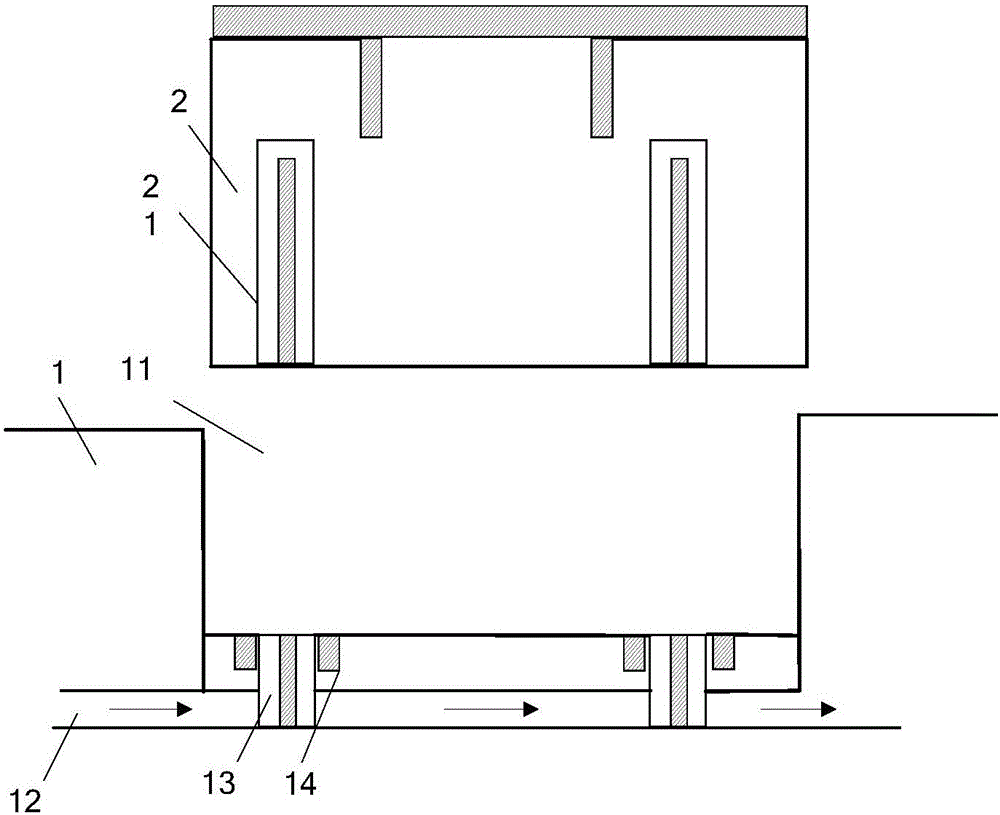
[0030] figure 1 It is a structural schematic diagram of the mosaic structure used for the filter cavity mold of the communication base station. This mosaic structure...


PUM


Abstract

The invention discloses an inlaying structure for a telecommunication base station filter cavity and a production method thereof. The inlaying structure comprises a mold body and an insert. A groove is formed in the middle of the mold body; a cooling water channel and at least one vertical cooling groove are formed in the mold body; the vertical cooling grooves are both located in the bottom of the groove; the shape and size of the groove are the same as those of the insert; the depth of the groove is equal to or smaller than the height of the insert; and vertical cooling grooves are formed in the insert. When the insert is mounted in the groove of the mold body, the vertical cooling grooves of the mold body and the vertical cooling grooves of the insert are matched and in correspondence in the vertical direction. During using of the inlaying device, when products are remodeled or improved or when casting points on the surface of the filter cavity are worsened and influence the grinding process to be not capable of bearing any more, the surface quality can be improved quickly only by changing an insert prepared in advance, and the grinding workload is reduced. The inlaying structure can effectively save the production cost while guaranteeing the forming quality.

Description

technical field [0001] The invention relates to the field of die-casting production, and relates to an inlay structure and a production method for a filter cavity mold for a communication base station. Background technique [0002] When the filter cavity castings for communication base stations are modified and upgraded, the modification needs are often achieved by making appropriate adjustments to the structure of the filter cavity, and the other features of the castings are not changed. Generally, the development of new products will Investing in a new die-casting mold requires a long cycle and a large investment, especially when the new product is not finalized and there is no need to invest in a new mold. In addition, the surface quality of the filter cavity is an important key that affects the power and energy efficiency of the communication base station. Customers have strict requirements on the casting points in the filter cavity. Light particles are often removed man...

Claims


Application Information

Patent Timeline
Patent Type & Authority Applications(China)
IPC IPC(8): B22D17/22
CPCB22D17/229
Inventor 任怀德张莹李谷南于永香王继成刘念康玉龙王恒德
Owner ZHUHAI RUNXINGTAI ELECTRICAL
Learn More