
Precoated sand regenerating production line

A production line and technology of coated sand, applied in the field of iron and steel casting, can solve the problems of wasting natural resources and polluting the environment by the waste of coated sand, and achieve the effect of reducing production costs and reducing environmental pollution

Inactive Publication Date: 2016-11-09
YUZHOU KUNLUN MOLD CO LTD
View PDF0 Cites 7 Cited by
  • Summary
  • Abstract
  • Description
  • Claims
  • Application Information

AI Technical Summary

Problems solved by technology

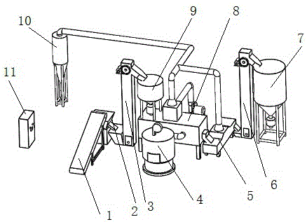
[0003] In the existing coated sand casting process, the coated sand forms waste to pollute the environment and waste natural resources. The present invention proposes a coated sand regeneration method, which is characterized in that it includes the following steps: 1. 2. Sieve the crushed material; 3. Use the conveyor to send the sieved sand to the elevator; 4. Use the elevator to send the sieved sand to the regeneration furnace; 5. The regeneration furnace sends the regenerated sand into the screening machine; 6. The regenerated sand is sent into the silo by conveying equipment; the step 1 is to use the sand shell or sand core made by the coated sand casting method, After the casting process, the discarded sand shells and sand cores are crushed with a pulverizer; the step 2 is to remove excess impurities according to the use requirements of the coated sand, and leave reusable sand; the step 3 is to Use conveying equipment to send the screened sand into the feed hopper of the elevator; the step 4 is to use the lifting equipment to send the sand to the upper feed port of the regeneration furnace; the step 5 is to pass the sand through the regeneration furnace After heating and drying, send it out of the regeneration furnace and enter the screening equipment for re-screening; the step 6 is to send the qualified regenerated sand into the silo for standby; all the above steps are realized by using the coated sand regeneration production line

Method used


Image

  • Precoated sand regenerating production line

Examples


Embodiment Construction

[0009] In order to further illustrate the technical solution of the present invention, the specific implementation of the present invention is now described in conjunction with the accompanying drawings. According to the scale of coated sand casting, the production capacity of the coated sand regeneration production line is selected, that is, the amount of coated sand waste processed per unit time , so as not to cause waste of production capacity or the phenomenon of not being able to meet production needs; select commercially available pulverizers and screening machines in this industry as raw material pulverizers and raw material screening machines 1, and install them on the feed port side of the raw material conveyor 2 ; Select the commercially available general belt conveyor in this industry as the raw material conveyor 2 in this example, and install it on the discharge port one end of the raw material pulverizer and the raw material screening machine 1, and connect its disc...


PUM


Abstract

The invention discloses a precoated sand regenerating production line and belongs to the field of steel casting. The precoated sand regenerating production line comprises a pulverizer, a raw material sieving machine, a raw material conveyor, a raw material elevator, a hot blast heater, a finished product sieving machine, a finished product elevator, a finished product stock bin, a regenerating furnace, a regenerating furnace feeder, a dust removal system and a control system, wherein the pulverizer is mounted at the front end of the raw material sieving machine; the raw material sieving machine is mounted between the pulverizer and the raw material conveyor; the raw material conveyor is mounted between th raw material sieving machine and the raw material elevator; the raw material elevator is mounted at the front end of the regenerating furnace; the hot blast heater is mounted on the side edge of the regenerating furnace; and the control system is mounted on a console and is connected with all functional parts. The precoated sand regenerating production line has the characteristics of realizing reutilization of precoated sand, reducing environmental pollution and lowering production cost.

Description

technical field [0001] The invention belongs to the field of iron and steel casting, in particular to a coated sand regeneration production line. Background technique [0002] Coated sand casting is a kind of casting process. Its principle is to use the characteristics of coated sand to use the corresponding mold to make sand shells and sand cores with the same shape and size as the parts to be cast. Molten iron is poured into the shell to form the blank of the workpiece to be cast; the coated sand is made of foundry sand with appropriate additives, and resin substances with adhesive properties are added to ensure the strength and air permeability of the sand shell or sand core , these substances are heated and pressurized during the molding process of the sand shell or sand core, and will adhere to the surface of the sand grains. When the casting process is completed, the sand shell and sand core will become waste after the workpiece blank is taken out. These wastes increa...

Claims


Application Information

Patent Timeline
IPC IPC(8): B22C5/00B22C5/04B22C5/06B22C5/16
CPCB22C5/00B22C5/04B22C5/06B22C5/16
Inventor 李向阳
Owner YUZHOU KUNLUN MOLD CO LTD
Learn More