anorectal intubation

A technology of intubation and anorectum, which is applied in the direction of rectoscope, rectal electron microscope, sigmoidoscope, etc. It can solve the problems of inconvenient colonoscope tube insertion, great pain for patients, and loss of patience for doctors, so as to reduce the qualified rate of products and reduce production costs , Reduce the effect of processing difficulty

Active Publication Date: 2017-09-19
JIANGSU RUISHANG MEDICAL DEVICES +1
View PDF9 Cites 0 Cited by
  • Summary
  • Abstract
  • Description
  • Claims
  • Application Information

AI Technical Summary

Problems solved by technology

Since the time of colonoscopy is generally about 20 minutes to 40 minutes, the sphincter contraction will cause fatigue for a long time, so the patient is relatively hard, and after the sphincter contraction clamps the colonoscope tube, it will also increase the distance between the colonoscope tube and the anus. The friction resistance between them makes it difficult for the doctor to continue to insert the colonoscope tube into the patient's anus
[0004] In addition, among the patients undergoing colonoscopy, many of them are relatively older. The sphincter contractility of these patients is weak, and they are no longer able to clamp the colonoscopy tube.
Therefore, these patients need to go through many attempts to insert the colonoscope tube into the anus during colonoscopy, and in the process of continuing to insert the colonoscope tube forward, due to insufficient contraction of the sphincter, it will cause intestinal The escape of gas or liquid in the intestinal tract of the endoscopic tube is not only unfavorable for the continued insertion of the endoscopic tube, but also leads to a longer inspection operation time, greater pain for the patient, and even causes the operating doctor to lose Patience; in addition, when the gas in the intestinal tract escapes from the anus, it will make noises, which will make the patient and the doctor very embarrassed, and objectively affect the mood of the doctor, thus affecting the effect of examination and treatment

Method used


Image

  • anorectal intubation

Examples


Embodiment Construction

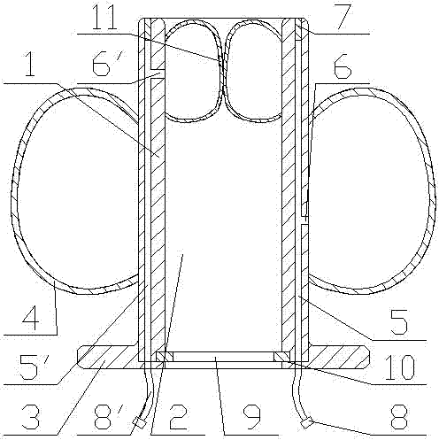
[0034] Such as figure 1As shown, the present invention includes an intubation body 1, the center of the intubation body 1 is provided with an intubation through hole 2, and the outer end of the intubation body 1 is provided with a rib 3 outwards, and the intubation body 1 The outer wall of the airbag A4 is provided with an airbag A4, and when the airbag A4 is inflated, the side of the airbag A4 facing the rib 3 and the rib 3 will clamp and relatively fix the skin and muscle at the anus; An airbag B11 is provided at the end far away from the rib 3, and when the airbag B11 is inflated, the intubation through hole 2 is closed; the airbag A4 is a ring structure placed around the intubation body 1, and the airbag B11 is a ring structure around the intubation body 1. An annular structure placed on the inner wall of the intubation through hole 2; the outer end of the tube wall of the intubation body 1 is respectively provided with a trachea through hole A5 and a trachea through hole ...


PUM


Abstract

The invention discloses an anorectal cannula. The center of a cannula body is provided with a cannula hole. The outer end of the cannula body is provided with an outward retaining edge. The outer side wall of the cannula body is provided with an air bag A. After the air bag A is inflated and expands, the side of the air bag A, facing the retaining edge, and the retaining edge clamp skin and muscles on an anus mouth, and the cannula is fixed relatively. One end in the cannula hole, far away from the retaining edge, is provided with an air bag B. After the air bag B is inflated and expands, the cannula hole is sealed. Known from the structure of the anorectal cannula, through action of the air bag A and a retaining plate, the retaining plate prevents the cannula body from sliding into an anorectum. After the air bag A is inflated, an intestinal tract wall is extruded, the outer side of the cannula body and the intestinal tract wall are sealed, and the intestinal tract wall is abutted, preventing the cannula body from sliding outward from an intestinal tract, so as to ensure that a colonoscopy tube can be continuously stuffed in an intestine, and ensure that the cannula body can be fixed on the anus mouth of a patient.

Description

technical field [0001] The invention relates to the field of colonoscopy examination and treatment, in particular to an anorectal cannula. Background technique [0002] Colonoscopy is to use a flexible fiber tube with a length of about 140 cm, a light source and a microelectronic camera at the end, slowly enter the large intestine from the anus, to check the lesions, tumors or ulcers in the large intestine, and take tissue tests if necessary Or perform colorectal polypectomy for examination and treatment. [0003] When the colonoscope tube enters the intestinal tract, it usually enters the scope from the anus, and the end of the colonoscope tube will first inject a little gas or water into the intestine at the front end, so that the intestinal wall at the front end will open, and then the colonoscope tube will go into the intestine. Forward insertion; each time the colonoscope tube is inserted forward, the bowel needs to be insufflated with gas. After the gas is poured int...

Claims


Application Information

Patent Timeline
Patent Type & Authority Patents(China)
IPC IPC(8): A61B1/00A61B1/31
CPCA61B1/00131A61B1/00154A61B1/31
Inventor 朱步兵王昕盛剑秋
Owner JIANGSU RUISHANG MEDICAL DEVICES
Why Eureka
Try Eureka