
shell integrator

A technology of integrators and small lenses, applied in the field of light engines, can solve problems such as heat generation and low efficiency, and achieve high optical efficiency and real-time color/luminous flux adjustment effects

Active Publication Date: 2019-06-21
LIGHT PRESCRIPTIONS INNOVATORS
View PDF10 Cites 0 Cited by
  • Summary
  • Abstract
  • Description
  • Claims
  • Application Information

AI Technical Summary

Problems solved by technology

Combining blue LEDs with phosphors that down-convert some of the blue light to longer wavelengths has been proposed, but this is inefficient and heat-generating, and the light produced is not considered white enough for all purposes

Method used


Image

  • shell integrator
  • shell integrator
  • shell integrator

Examples


Embodiment Construction

[0063] A better understanding of the various features and advantages of the present invention will be obtained by referring to the following detailed description of the embodiments of the invention and the accompanying drawings, which illustrate exemplary embodiments that utilize the specific principles of the invention.

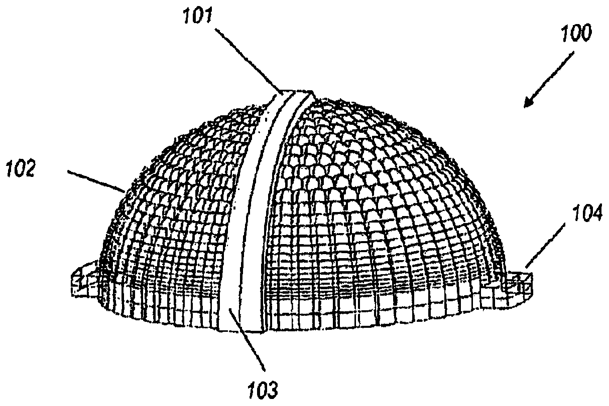
[0064] With reference to the attached drawings, the first figure 1 , one embodiment of the optic 100 includes a generally hemispherical shell integrator 102 with a light guide 103 extending from the zenith along a hemispherical curve down to the edge. At the zenith, the light guide 103 is provided with a reflective surface 301a (see image 3 ) to combine from a source at the center of the hemisphere (at figure 1 (not shown in ) is introduced into the light guide 103. The edges of the optic 100 may be provided with protruding lugs 104 or other formations to enable the optic 100 to be mounted as part of a light fixture. Such as figure 1 As shown, the light...


PUM


Abstract

A shell integrator includes a hollow transparent body having inner and outer surfaces formed as an array of lenslets. Each lenslet on the inner surface will image the common source area in the middle of the hollow body onto the corresponding lenslet on the outer surface. Each lenslet of the outer surface forms a virtual image of the corresponding lenslet of the inner surface of the common source area. An integrator has a light guide that follows the surface of the hollow body from an inlet end at the center region of the surface to an exit end at the edge of the hollow body. The light guide entrance end is shaped to receive light from the common source region and direct this light along the light guide. Another type of integrator is generally elongated and may be semi-cylindrical. Any of these integrators can have a stepped surface forming a Fresnel lens.

Description

[0001] Cross References to Related Applications [0002] This application claims the benefit of U.S. Provisional Patent Application No. 61 / 964520, filed January 6, 2014, by Benítez et al., entitled "Color / luminancetunable light engine with integrated light-guide feedback feature and sensor," which U.S. Provisional Patent This application is hereby incorporated by reference in its entirety. [0003] This application is related to co-pending U.S. Patent Application No. 2013 / 0194811, published August 1, 2013, entitled "Shell integrator," filed April 10, 2013 by Benítez et al. with application number 13 / 821823 , which is the national phase of International Patent Application No. WO 2012 / 040414 published on March 29, 2012 and claiming priority to U.S. Provisional Application No. 61 / 385,675 filed on September 23, 2010, all These patent applications are hereby incorporated by reference in their entireties. [0004] Some of the incorporations in this example are granted to et al., e...

Claims


Application Information

Patent Timeline
Patent Type & Authority Patents(China)
IPC IPC(8): G02B3/00F21V13/00
CPCF21V5/045F21V23/0457F21V5/008G02B3/0037G02B3/0062G02B6/00G02B27/0905G02B27/0961F21Y2115/10F21Y2113/13
Inventor P·贝尼特斯J·C·查威斯R·莫禾达诺A·茨韦特科维奇J·C·米纳诺W·法利科夫
Owner LIGHT PRESCRIPTIONS INNOVATORS
Learn More