Injection locking frequency divider circuit based on variable inductance value

A technology of injection locking and frequency divider, which is applied in the direction of electrical components, automatic power control, etc., can solve the problem of small frequency division range and use range, and achieve the effect of increasing the frequency division range

Inactive Publication Date: 2016-10-26
TSINGHUA UNIV
View PDF3 Cites 5 Cited by
  • Summary
  • Abstract
  • Description
  • Claims
  • Application Information

AI Technical Summary

Problems solved by technology

[0005] The existing injection-locked frequency divider has always been the main factor limiting its application range due to its small frequency division range.

Method used


Image

  • Injection locking frequency divider circuit based on variable inductance value
  • Injection locking frequency divider circuit based on variable inductance value
  • Injection locking frequency divider circuit based on variable inductance value

Examples


Embodiment Construction

[0015] In order to make the purpose, technical solution and features of the present invention clearer, the present invention will be described in detail below in conjunction with the accompanying drawings and embodiments.

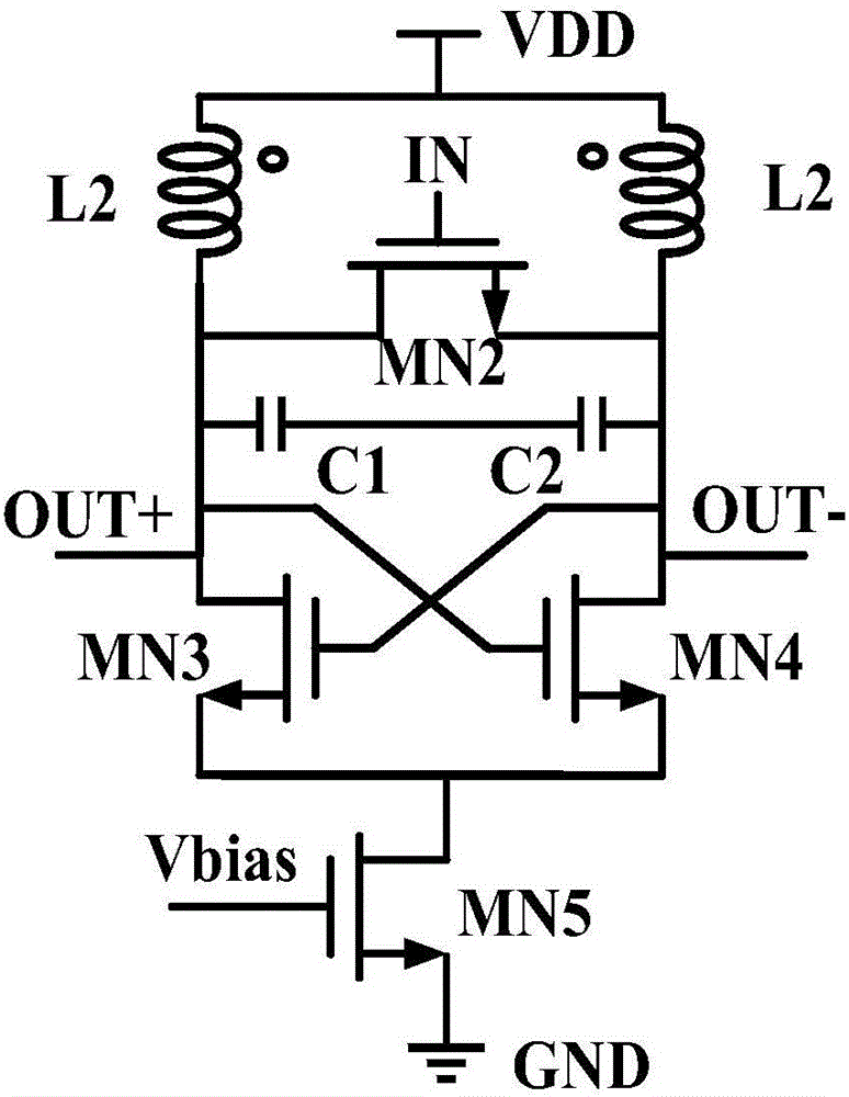
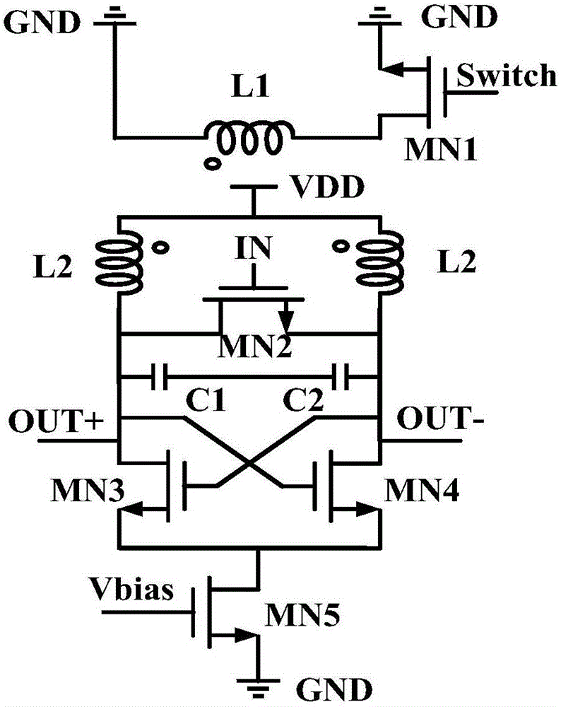
[0016] A kind of injection-locked frequency divider circuit structure based on variable inductance value proposed by the present invention, such as figure 2 As shown, it is characterized in that the injection-locked frequency divider circuit consists of: five NMOS transistors, two capacitors, and two inductors (wherein L1 is a common inductor, and L2 is a differential inductor); wherein, the inductor L1 and the transistor MN1 are composed of The first current loop, the remaining four transistors, two capacitors and the differential inductor L2 form the second current loop, and the coupling between the two current loops occurs through two inductors; the connection relationship of the above-mentioned components is: the inductor L1 The tap end is grounded to ...


PUM


Abstract

The invention discloses an injection locking frequency divider circuit based on a variable inductance value, and belongs to the field of radio frequency and millimeter wave terahertz integrated circuit design. The circuit comprises five NMOS transistors, two capacitors and two inductors. A first current loop is formed by the inductors and a first transistor. A second current loop is formed by the other four transistors, two capacitors and a differential inductor. Coupling effect is generated between the two current loops through the two inductors. The inductance value of the circuit can be adjusted by switching the first transistor. Therefore, the frequency division range of a frequency divider is improved. According to the circuit, on the premise that the power consumption is kept unchanged, compared with the prior art, the circuit has the advantages that the frequency division range of the frequency divider is improved to a great extent, the wider frequency division range is provided in low power consumption, and the performance of a transceiver is improved.

Description

technical field [0001] The invention belongs to the field of radio frequency and millimeter-wave terahertz integrated circuit design, and in particular relates to the design of a frequency divider with low power consumption, high frequency and wide range in the millimeter-wave terahertz frequency band. Background technique [0002] Today, more than a hundred years after the development of wireless communication, resources in the 500MHz-5GHz frequency band in the field of military communication have become increasingly scarce. Although future quantum communication technology is worth looking forward to, it is still somewhat out of reach. The terahertz band, which was once "forgotten", integrates the advantages of microwave communication and optical communication, and has many characteristics such as high transmission rate, large capacity, strong directionality, high security and good penetration. The prospect of application is attractive, and it has become a hot spot for mini...

Claims


Application Information

Patent Timeline
Patent Type & Authority Applications(China)
IPC IPC(8): H03L7/18
CPCH03L7/18
Inventor 张雷朱新新王燕
Owner TSINGHUA UNIV
Why Eureka
Try Eureka