Array antenna source for transient electromagnetic tunnel advanced detection

A transient electromagnetic method and array antenna technology, applied in the field of array antenna sources, can solve the problems of fine detection of fissure-type disaster sources and difficulties in water conduction channels, and achieve the goal of improving exploration depth, high resolution, and signal-to-noise ratio Effect

Inactive Publication Date: 2016-10-26
CHANGAN UNIV
View PDF4 Cites 2 Cited by
  • Summary
  • Abstract
  • Description
  • Claims
  • Application Information

AI Technical Summary

Problems solved by technology

However, conventional transient electromagnetic methods and other geophysical exploration methods still have certain difficulties in finely detecting fissure-type disaster sources and water-conducting channels.

Method used


Image

  • Array antenna source for transient electromagnetic tunnel advanced detection
  • Array antenna source for transient electromagnetic tunnel advanced detection
  • Array antenna source for transient electromagnetic tunnel advanced detection

Examples


Embodiment Construction

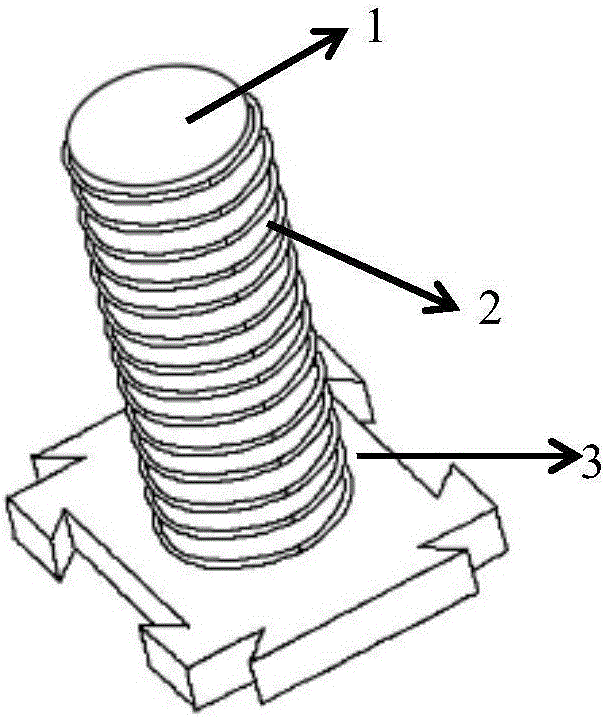
[0032] see Figure 2 to Figure 5 , the present embodiment provides an array antenna source aimed at the advanced prediction of the tunnel transient electromagnetic method, including several transmitting units, each transmitting unit has an external power supply behind it, and the transmitting unit is composed of a transmitting antenna, a helix and a base ,in:
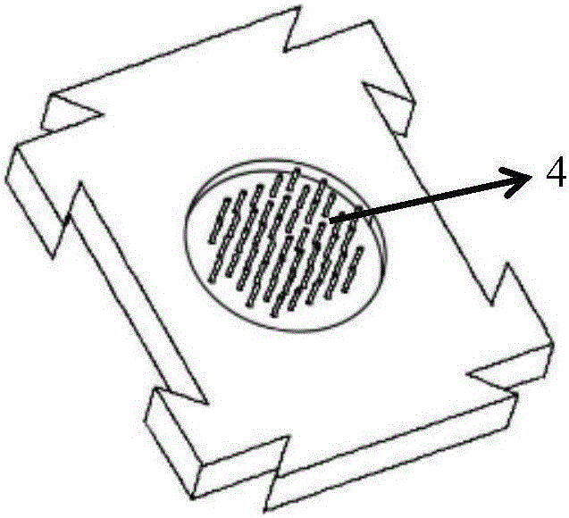
[0033] The helix is ​​wound around the transmitting antenna, and there is an isolation layer between the helix and the transmitting antenna to prevent current contact, and the helix can eliminate mutual inductance; one side of the depression in the center of the base is the access port for the external power supply, and the other side of the depression is There is an array of pins for inserting the transmitting antenna, and there are corresponding protrusions and depressions around the base for splicing several transmitting units into one.

[0034] Because each transmitting unit is closer, measures need to be taken on ...


PUM


Abstract

The invention discloses an array antenna source for advanced transient electromagnetic tunnel forecast. The array antenna source comprises multiple emission units, wherein the back of each emission unit is an external power source, the emission units respectively comprise an emission antenna, a spiral wire and a foundation, the spiral wire is wound at periphery of the emission antenna, an isolation layer is arranged between the spiral wire and the emission antenna to prevent current contact, the mutual inductance elimination effect is further realized, one side of a recess portion of a foundation center is an access port of the external power source, the other side of the access portion is provided with a needle array used for plugging the emission antennas, and periphery of the foundation has corresponding projections and recesses which are used for splicing the multiple emission units into one body. According to the array antenna source, emission field source intensity can be improved through changing source parameters and emission current intensity, exploration depth is improved, emission source pulse width is changed, high frequency harmonic wave components are improved, exploration precision is improved, high-resolution long distance exploration can be realized, and precise detection on a water guide channel in front of a tunnel face can be realized.

Description

technical field [0001] The invention belongs to the field of geophysical detection, and in particular relates to an array antenna source for advanced prediction of tunnel transient electromagnetic method. Background technique [0002] With the implementation of the country's "Western Development" strategy and the "Belt and Road" strategy, the construction of major infrastructure projects such as railway and road traffic projects, water conservancy and hydropower projects has developed rapidly and has been transferred to the western mountainous areas year by year. The most numerous and most difficult countries. With the construction of more and more tunnel projects, the geological conditions are becoming more and more complex. Unforeseen engineering geological disasters, such as water inrush, mud inrush, and collapse, are prone to occur during tunnel excavation. Water and mud inrush disasters will not only cause casualties and economic losses in various underground projects ...

Claims


Application Information

Patent Timeline
Patent Type & Authority Applications(China)
IPC IPC(8): G01V3/30
CPCG01V3/30
Inventor 李貅戚志鹏孙乃泉周建美郭建磊
Owner CHANGAN UNIV
Why Eureka
Try Eureka