Planetary drive reducer for tube mill and tube mill equipment

A planetary transmission and reducer technology, applied in mechanical equipment, transmission, gear transmission and other directions, can solve problems such as unfavorable energy saving, emission reduction, cost reduction, etc. Effect

Active Publication Date: 2019-04-30
成都名辰传动设备有限公司
View PDF7 Cites 0 Cited by
  • Summary
  • Abstract
  • Description
  • Claims
  • Application Information

AI Technical Summary

Problems solved by technology

[0004] The purpose of the present invention is to overcome the increase in volume and weight of the tube mill existing in the prior art. In the industry, the size of the matching reducer is simply enlarged according to the original structure, and the parallel shaft reducer is still used. Due to the tube mill and The size and weight of the reducer increase, especially the weight of the reducer reaches at least 60T. The volume and weight of the supporting motor are larger than before, and the output power requirements are higher. The manufacturing, transportation, structural installation, and site requirements of the reducer and motor The higher the requirements are, it is not conducive to energy saving, emission reduction, and cost reduction. At the same time, there are the above-mentioned deficiencies that the uneven load phenomenon affects the service life. A planetary transmission reducer for a tube mill and a tube mill equipment are provided. The planetary transmission reducer is relatively The existing parallel shaft reducer increases the transmission ratio and improves the transmission efficiency. Under the same output requirements, the planetary transmission reducer and the matching motor are smaller in size and lighter in weight, which can effectively overcome the existing partial load phenomenon and reduce the speed. The machine and the tube mill are directly connected, thus avoiding the severe impact and vibration caused by the different axes of the tube mill and the reducer center, making the output more stable and improving the service life

Method used


Image

  • Planetary drive reducer for tube mill and tube mill equipment
  • Planetary drive reducer for tube mill and tube mill equipment
  • Planetary drive reducer for tube mill and tube mill equipment

Examples


Embodiment 1

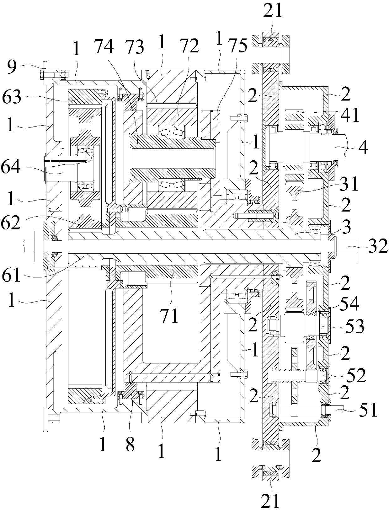
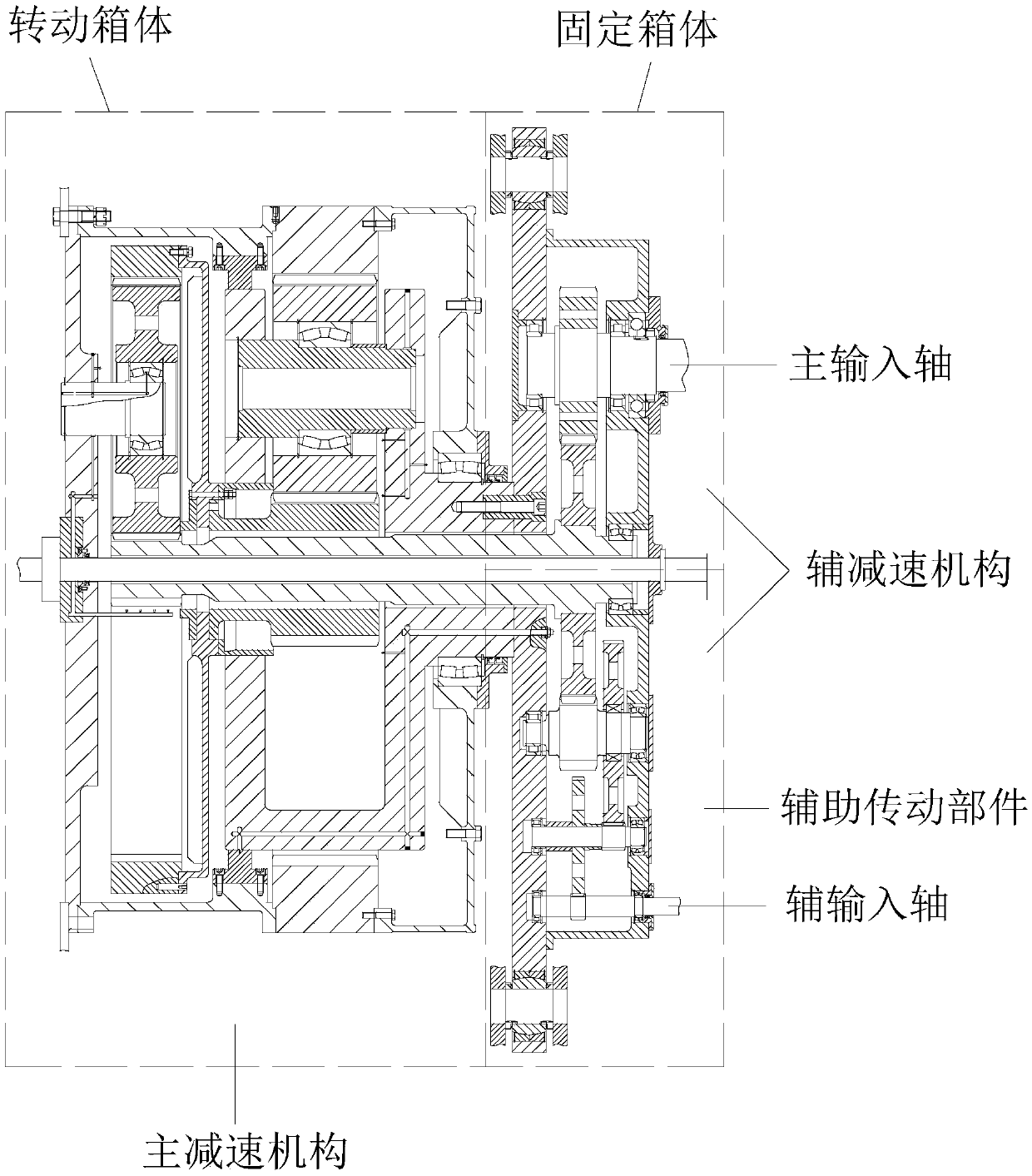
[0036] Such as Figure 2-3 As shown, a planetary transmission reducer for a tube mill according to the present invention includes a rotating box 1 and a fixed box 2 .

[0037] The fixed box 2 is provided with a central axis 3, and the central axis 3 extends out of the fixed box 2, and the rotating box 1 is connected to the extension of the central axis 3 and can rotate around it. Rotating box body 1 is provided with at least one stage of planetary transmission parts, and each stage of said planetary transmission parts includes a sun gear, a planetary gear, a planetary gear shaft, a planet carrier and an inner ring gear, and said sun gear in each stage of said planetary transmission parts The input and rotation of the wheel drive the inner ring gear to rotate and output, the inner ring gear of the first stage among the two adjacent planetary transmission parts is fixedly connected to the sun gear of the second stage, and the fixed box 2 is equipped with a The input shaft conne...

Embodiment 2

[0049] Such as Figure 2-4 As shown, a tube mill equipment according to the present invention includes a planetary transmission reducer for a tube mill as described in Embodiment 1.

[0050] The input shaft located in the fixed box 2 of the planetary transmission reducer 05 is connected to the motor 04, and the rotating box 1 is connected to the tube mill 01 through a flange 9 and bolts.

[0051] As a preference of this embodiment, the input shaft is connected to a universal joint, and the universal joint is connected to the motor 04 .

[0052] The main transmission power transmission route of the tube mill equipment is:

[0053] Main motor→universal joint→main input shaft 4→pinion gear 41→big gear 31→central shaft 3→primary sun gear 61→primary planetary gear 62→primary internal ring gear 63→secondary sun gear 71→two Stage planetary gear 72 → secondary ring gear 73 → rotating box 1 → tube mill 01.

[0054] The auxiliary transmission power transmission route of the tube mill...


PUM


Abstract

The invention discloses a planetary transmission reducer for a tube mill. The planetary transmission reducer comprises a rotating box and a fixed box, wherein a central shaft is arranged inside the fixed box; planetary transmission parts are arranged inside the rotating box; sun gears in the planetary transmission parts input force and rotate to drive inner gear rings to rotate and output force; and the rotating box is connected with the tube mill. Through the application of the reducer, planetary gear transmission is utilized, so that compared with a conventional parallel shaft reducer, the planetary transmission reducer has the advantages that the transmission ratio is increased, the transmission efficiency is improved, under the same output requirement, the sizes of the planetary transmission reducer and a matched motor are smaller, and the weights are lighter; a planet carrier relative mounting base is fixedly arranged, and after the sun gears input force, the planetary transmission parts transmit the force to drive the last stage inner gear ring fixedly connected with the rotating box to rotate; and the structure has flexible transmission property, the conventional eccentric load phenomenon can be effectively overcome, the impact vibration is reduced, the output is more stable, the service life is prolonged, the structure is simple, the manufacturing and transportation are convenient, the cost is low, and the popularization is facilitated.

Description

technical field [0001] The invention relates to a speed reducer, in particular to a planetary transmission speed reducer for a tube mill and tube mill equipment. Background technique [0002] Tube mill is an important fine grinding equipment in modern industry, widely used in building materials, metallurgy, mineral processing, electric power and chemical industries to grind cement and other materials, such as figure 1 Shown is the connection schematic diagram of the existing tube mill 01 and reducer 03, wherein the tube mill 01 is connected to the diaphragm coupling 02, the diaphragm coupling 02 is connected to the reducer 03, and the reducer 03 is connected to the motor 04, wherein the reducer 03 used is a parallel shaft reducer, which adopts parallel shaft transmission, that is, the input shaft of the reducer 03 is connected to the motor 04, and the input shaft in the reducer 03 is connected to the first-stage reduction gear and the first-stage reduction gear located at th...

Claims


Application Information

Patent Timeline
Patent Type & Authority Patents(China)
IPC IPC(8): F16H1/32F16H1/36F16H57/04B02C17/08B02C17/18B02C17/24
CPCB02C17/08B02C17/1815B02C17/24F16H1/32F16H1/36F16H57/0412F16H57/043F16H2001/325
Inventor 冉学平苏燕
Owner 成都名辰传动设备有限公司
Why Eureka
Try Eureka