Concave flow distribution plate and reactor with same
An air distribution plate and air distribution technology, which is applied in chemical instruments and methods, chemical/physical processes, etc., can solve the imbalance of circumferential flow and axial flow, cannot form a three-dimensional bed as a whole, and the force of a circular plate is stronger than that of a shell. Body difference and other problems, to achieve the effect of no dead zone, safe and scientific space layout, and safe protection of the shell wall
- Summary
- Abstract
- Description
- Claims
- Application Information
AI Technical Summary
Problems solved by technology
Method used
Image
Examples
Embodiment 1
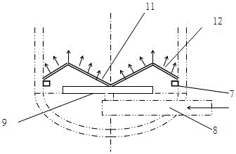
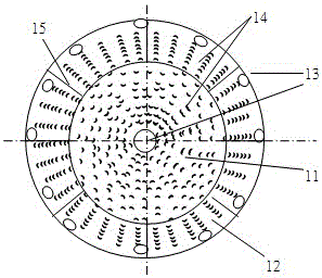
[0039] One of the specific implementations of a concave airflow distribution plate of the present application, refer to figure 1 and figure 2 As shown, it is formed by the improvement of a flat airflow distribution plate. The innovation of the present application is that the concave airflow distribution plate 10 includes a concave structure that is recessed downward along the central axis of the concave airflow distribution plate 10 11, and the bent structure 12 formed by bending the peripheral side of the concave air distribution plate 10 downward.
[0040] Specifically, the concave structure 11 is an inverted cone structure. The concave air flow distribution plate 10 is composed of a concave structure in the middle and a bent structure 12 on the peripheral side to form an M-shaped air flow distribution plate. Studies have shown that the M-shaped structure has radial elasticity and can adapt to the deformation of the reactor. Displacement without being distorted and deform...
Embodiment 2
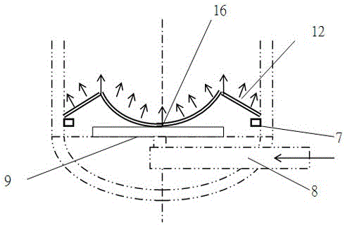
[0051] The second specific embodiment of a concave airflow distribution plate of the present application, the main technical solution of this embodiment is the same as that of embodiment 1, and the features not explained in this embodiment adopt the explanation in embodiment 1, here No further details will be given. refer to image 3 As shown, the difference between this embodiment and Embodiment 1 is that the concave structure 11 is a spherical structure 16 . It can make the process gas flow upward evenly in the reactor, and at the same time make the generated material particle products collect and discharge from the bottom through the concave air flow distribution plate, and can also resist vibration fatigue caused by large material flow and fast air velocity. An anti-sediment distribution plate that satisfies pressure drop stability and good fluidization quality.
Embodiment 3
[0053] The third specific implementation mode of a concave air distribution plate of the present application, the main technical solution of this embodiment is the same as that of embodiment 1, and the features not explained in this embodiment adopt the explanation in embodiment 1, here No further details will be given. refer to Figure 4 As shown, the difference between this embodiment and Embodiment 1 is that the concave structure 11 is a concave structure 17 composed of symmetrically arranged convex hyperboloids. It can make the process gas flow upward evenly in the reactor, and at the same time make the generated material particle products collect and discharge from the bottom through the concave air flow distribution plate, and can also resist vibration fatigue caused by large material flow and fast air velocity. An anti-sediment distribution plate that satisfies pressure drop stability and good fluidization quality.
PUM
 Abstract
Description
Claims
Application Information
 - R&D
- Intellectual Property
- Life Sciences
- Materials
- Tech Scout
- Unparalleled Data Quality
- Higher Quality Content
- 60% Fewer Hallucinations
Browse by: Latest US Patents, China's latest patents, Technical Efficacy Thesaurus, Application Domain, Technology Topic, Popular Technical Reports.
© 2025 PatSnap. All rights reserved.Legal|Privacy policy|Modern Slavery Act Transparency Statement|Sitemap|About US| Contact US: help@patsnap.com


