
Shockproof buffer device for batteries for electric vehicle

A technology of electric vehicles and buffer devices, which is applied in the direction of electric power devices, power devices, battery pack components, etc., and can solve problems such as battery pack collisions

Inactive Publication Date: 2016-10-12
天津中科先进技术产业有限公司
View PDF0 Cites 7 Cited by
  • Summary
  • Abstract
  • Description
  • Claims
  • Application Information

AI Technical Summary

Problems solved by technology

[0004] The purpose of the present invention is to address the technical defects of the prior art, and to provide a battery shock-proof buffer device for electric vehicles, so as to solve the technical problem that the electric vehicle battery pack in the prior art collides when the vehicle is running

Method used


Image

  • Shockproof buffer device for batteries for electric vehicle

Examples


Embodiment 1

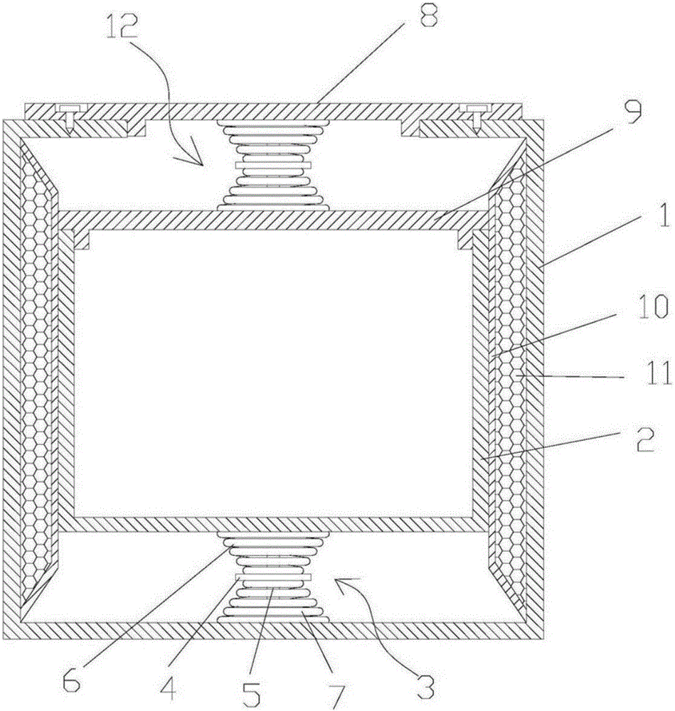
[0020] A battery shockproof buffer device for electric vehicles, comprising a box body 1, a metal box 2, a lower cavity 3, a rubber plate 4, a first spring 5, a second spring 6, a boss 7, a box cover 8, a box cover 9, Housing 10, phase change material 11, and upper cavity 12, in which the case cover 8 is riveted to the upper end of the case 1, the case 10 is fixedly connected to the inner wall of the case 1, and the case 10 and the inner wall of the case 1 form a closed inner cavity , the cavity is filled with a phase change material 11, the metal box 2 is built in the box body 1, the box cover 9 is hinged on one side of the upper end surface of the metal box 2, and the outer surface of the metal box 2 and the outer surface of the housing 10 In contact with each other, the metal box 2 and the shell 10 divide the inner space of the box body 1 into two parts, the upper cavity 12 and the lower cavity 3, the boss 7 is fixedly connected to the inner bottom surface of the box body 1,...

Embodiment 2

[0027] A battery shockproof buffer device for electric vehicles, comprising a box body 1, a metal box 2, a lower cavity 3, a rubber plate 4, a first spring 5, a second spring 6, a boss 7, a box cover 8, a box cover 9, Housing 10, phase change material 11, and upper cavity 12, in which the case cover 8 is riveted to the upper end of the case 1, the case 10 is fixedly connected to the inner wall of the case 1, and the case 10 and the inner wall of the case 1 form a closed inner cavity , the cavity is filled with a phase change material 11, the metal box 2 is built in the box body 1, the box cover 9 is hinged on one side of the upper end surface of the metal box 2, and the outer surface of the metal box 2 and the outer surface of the housing 10 In contact with each other, the metal box 2 and the shell 10 divide the inner space of the box body 1 into two parts, the upper cavity 12 and the lower cavity 3, the boss 7 is fixedly connected to the inner bottom surface of the box body 1,...


PUM

PropertyMeasurementUnit
Thicknessaaaaaaaaaa

Abstract

The invention provides a shockproof buffer device for batteries for an electric vehicle. The device is provided with an external cabinet protection structure on the basis of a conventional metal box containing a battery pack; the metal box is internally arranged into a cabinet; and the metal box is connected with the inner wall of the cabinet by a spring assembly, so that buffer protection on the battery pack is achieved through the buffer action of springs. On this basis, in order to reduce noise generated by spring expansion in the driving process while the buffer range is ensured, the spring assembly is separated through a rubber plate, so that the noise of the springs is reduced. Meanwhile, a shell filled with a phase change material is arranged in the cabinet and is in contact with the metal box containing the battery pack, so that the heat dissipation effect is improved to a certain extent by the constant-temperature characteristic of the phase change material. An advantageous technical progress is achieved through outstanding technical improvement; and the shockproof buffer device has extremely high promotion potential.

Description

technical field [0001] The invention relates to the technical field of electric vehicles, in particular to a battery shockproof buffer device for electric vehicles. Background technique [0002] An electric vehicle (BEV) refers to a vehicle that is powered by a vehicle-mounted power supply, drives the wheels with a motor, and meets the requirements of road traffic and safety regulations. Due to its smaller impact on the environment than traditional cars, its prospects are widely optimistic, but the current technology is still immature. Pure electric vehicles, compared with fuel vehicles, the main difference (difference) lies in the four major components, drive motor, speed controller, power battery, and on-board charger. Electric vehicles use fuel cells as the power source. The chemical reaction process of the battery will not produce harmful products, so the pollution of electric vehicles is extremely small. Since the energy conversion efficiency of the battery is 2 to 3 t...

Claims


Application Information

Patent Timeline
IPC IPC(8): H01M2/10B60K1/04H01M50/249
CPCB60K1/04H01M50/20Y02E60/10
Inventor 吴正斌曹晓燕胡贺宾
Owner 天津中科先进技术产业有限公司
Learn More