
discharge lamp

A technology for discharge lamps and discharge tubes, which is applied to discharge tubes/lamp parts, gas discharge lamp parts, and main electrodes of discharge tubes, etc., can solve the problems of reduced electron emission characteristics and exhaustion of emitters.

Active Publication Date: 2019-07-09
ORC MFG
View PDF4 Cites 0 Cited by
  • Summary
  • Abstract
  • Description
  • Claims
  • Application Information

AI Technical Summary

Problems solved by technology

Therefore, flickering occurs due to depletion of emitters on the surface of the front end of the cathode, degraded electron emission characteristics

Method used


Image

  • discharge lamp
  • discharge lamp
  • discharge lamp

Examples


Embodiment Construction

[0014] Hereinafter, embodiments of the present invention will be described with reference to the drawings.

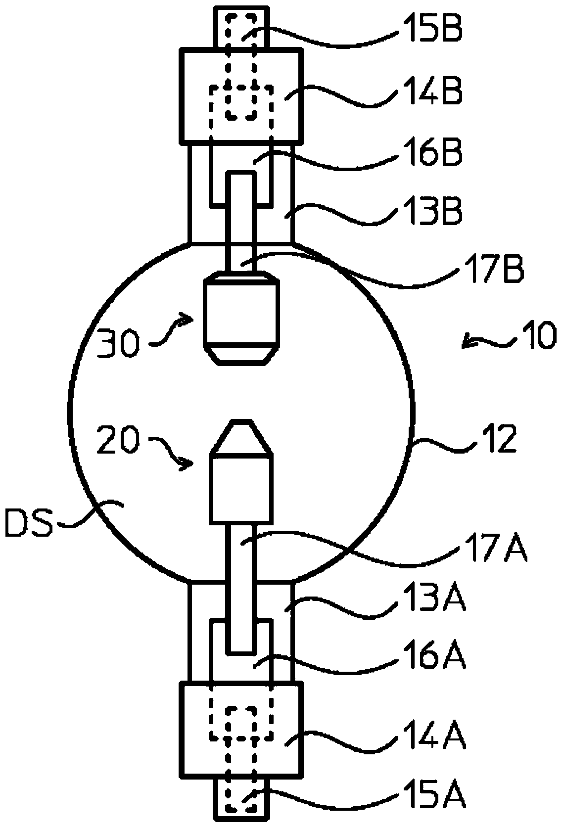
[0015] figure 1 It is a top view schematically showing the short-arc discharge lamp of the first embodiment.

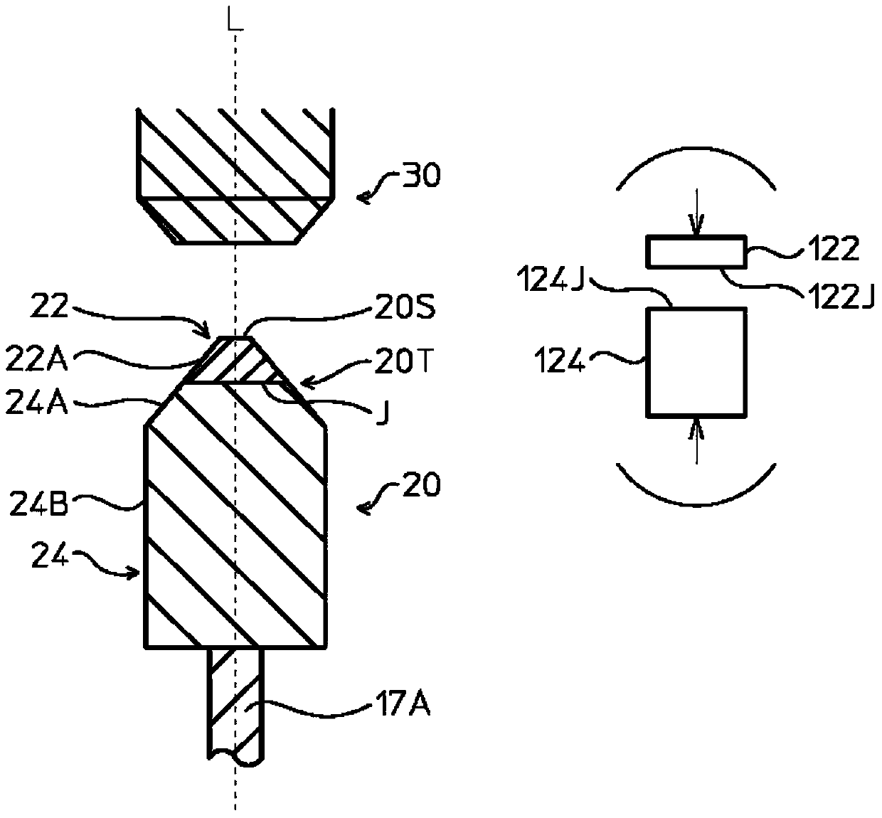
[0016] The short-arc discharge lamp 10 is a discharge lamp that can be used as a light source of a pattern forming exposure device (not shown), and includes a discharge tube (light emitting tube) 12 made of transparent quartz glass. In the discharge tube 12, the cathode 20 and the anode 30 are arranged facing each other with a predetermined interval therebetween.

[0017] On both sides of the discharge tube 12, sealing tubes 13A, 13B made of quartz glass are provided integrally with the discharge tube 12 so as to face each other, and both ends of the sealing tubes 13A, 13B are sealed by caps 14A, 14B. Here, the discharge lamp 10 is arranged along the vertical direction so that the anode 30 is on the upper side and the cathode 20 is on the lower side.

[0018...


PUM


Abstract

To provide a discharge lamp in which electrodes are formed by joining different metal members, which prevents depletion of an emitter substance and suppresses flicker of arc discharge. In a discharge lamp in which a cathode and an anode are oppositely arranged in a discharge vessel, the cathode is formed by solid-state bonding of a plurality of metal parts including a front-side part containing an emitter substance and a rod supported by an electrically conductive electrode. The supported rear member reduces the amount of heat transferred from the front member to the rear member at the vicinity of at least one joint surface between the metal members.

Description

technical field [0001] The present invention relates to a discharge lamp used in an exposure device and the like, and particularly relates to an electrode structure of a high-output discharge lamp such as a short-arc discharge lamp. Background technique [0002] Conventionally, in a discharge lamp, an emitter substance is added to a cathode to improve electron emission characteristics. Thorium oxide (ThO 2 ), but thorium oxide is radioactive. Therefore, use should be controlled as much as possible, and a discharge lamp in which only the tip of the cathode contains an emitter substance (thorium oxide) as in Patent Document 1 has been developed. [0003] Patent Document 1: Japanese Patent No. 5316436 [0004] However, in the conventional cathode structure, the emitter contained in the front end of the cathode cannot be effectively used. When the discharge lamp is turned on, the temperature of the inside of the cathode tip is lower than that of the surface of the cathode ti...

Claims


Application Information

Patent Timeline
Patent Type & Authority Patents(China)
IPC IPC(8): H01J61/06H01J1/144H01J1/16
CPCH01J1/144H01J1/16H01J61/06
Inventor 早川壮则内山满博馆林和人
Owner ORC MFG
Learn More