
Flexible display

A flexible display and flexible display technology, applied in the direction of instruments, electronic equipment, nonlinear optics, etc., can solve problems such as uneven stress distribution, regional wear, and complete failure

Active Publication Date: 2016-10-12
SAMSUNG DISPLAY CO LTD
View PDF6 Cites 44 Cited by
  • Summary
  • Abstract
  • Description
  • Claims
  • Application Information

AI Technical Summary

Problems solved by technology

[0003] However, since such a flexible display has a structure in which multiple layers are stacked, when the display is bent, stress may Uneven distribution
Because unevenly distributed stress is concentrated in one area, that area can experience premature wear, leading to damage or complete failure

Method used


Image

  • Flexible display
  • Flexible display
  • Flexible display

Examples


Embodiment Construction

[0032] Hereinafter, exemplary embodiments will be described in detail with reference to the accompanying drawings. However, in describing the embodiments, descriptions of known functions or configurations will be omitted to clarify the description of the subject matter.

[0033] The drawings and descriptions are to be regarded as illustrative in nature and not restrictive. Throughout the specification, the same reference numerals denote the same elements. In addition, the size and thickness of each component shown in the drawings may be exaggerated for clarity and convenience of description, but the described technology is not limited thereto.

[0034] It will be understood that when an element such as a layer, film, region, or substrate is referred to as being "on" another element, it can be directly on the other element or intervening elements may also be present.

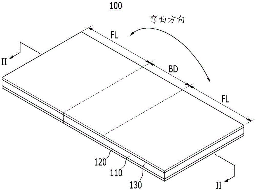
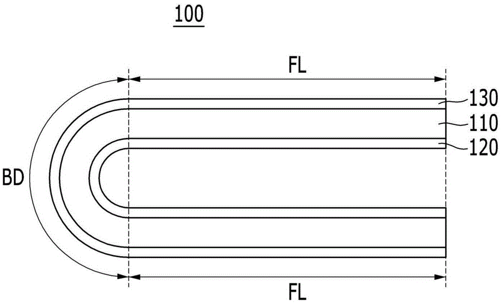
[0035] figure 1 is a perspective view of a flexible display according to an example embodiment. figure 2 ...


PUM


Abstract

A flexible display is disclosed. In one aspect, the flexible display includes a window layer including a bending area and a non-bending area and a flexible display panel formed over a surface of the window layer and configured to display images. The bending area includes a plurality of cut portions which are configured to be at least partially separated along a plurality of cut lines formed therebetween.

Description

technical field [0001] The described technology generally relates to a flexible display capable of preventing damage due to bending of the display and maintaining optical properties even when the display is bent. Background technique [0002] Currently, commonly known display devices (each using a unique display technology) include Liquid Crystal Displays (LCDs), Plasma Display Panels (PDPs), Organic Light Emitting Diode (OLED) displays, Field Effect Displays (FEDs), Electrophoretic Displays ( EPD) etc. Techniques for forming these types of display devices using flexible materials are currently being researched. Since display devices formed using flexible materials can be used to develop new devices such as e-books and e-papers, these flexible displays are expected to be widely used in various applications. [0003] However, since such a flexible display has a structure in which multiple layers are stacked, when the display is bent, stress may Uneven distribution. Becaus...

Claims


Application Information

Patent Timeline
Patent Type & Authority Applications(China)
IPC IPC(8): G09F9/30G02B1/14
CPCG09F9/301G06F1/1652G06F1/1641C09K2323/05B32B2457/20B32B2457/206B32B2457/202B32B3/30C09K2323/051G02F1/133305
Inventor 柳安娜金武谦
Owner SAMSUNG DISPLAY CO LTD
Learn More