
Liquid crystal display panel and display device

A liquid crystal display panel and panel technology, applied in nonlinear optics, instruments, optics, etc., can solve the problem of pixel structure light leakage and achieve the effect of improving the light leakage problem

Inactive Publication Date: 2016-10-12
BOE TECH GRP CO LTD +1
View PDF4 Cites 26 Cited by
  • Summary
  • Abstract
  • Description
  • Claims
  • Application Information

AI Technical Summary

Problems solved by technology

[0005] Embodiments of the present invention provide a liquid crystal display panel and a display device to solve the problem of light leakage in the dark state of the pixel structure corresponding to the improved FFS display mode existing in the prior art

Method used


Image

  • Liquid crystal display panel and display device
  • Liquid crystal display panel and display device
  • Liquid crystal display panel and display device

Examples


Embodiment Construction

[0027] In order to make the purpose, technical solutions and advantages of the present invention clearer, the present invention will be further described in detail below in conjunction with the accompanying drawings. Obviously, the described embodiments are only some of the embodiments of the present invention, rather than all of them. Based on the embodiments of the present invention, all other embodiments obtained by persons of ordinary skill in the art without making creative efforts belong to the protection scope of the present invention.

[0028] The technical solution involved in the present invention will be described in detail through specific examples below, and the present invention includes but is not limited to the following examples.

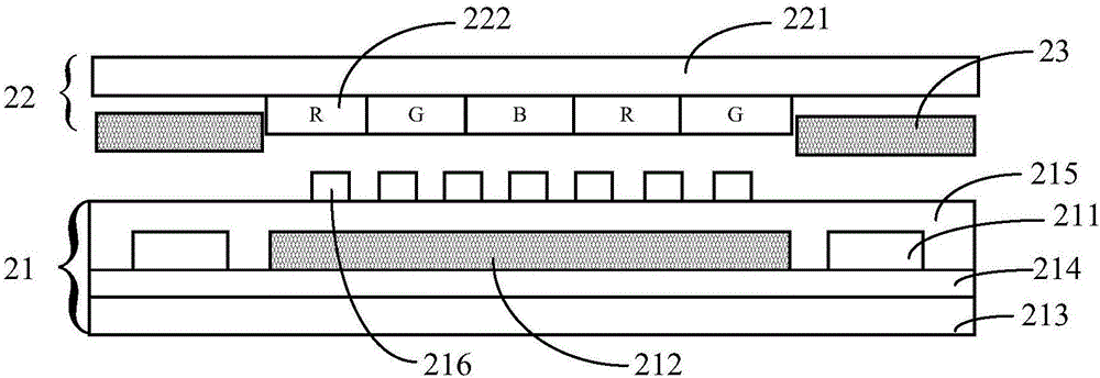
[0029] Such as figure 2 As shown, it is a schematic cross-sectional structure diagram of a liquid crystal display panel provided by an embodiment of the present invention. It should be noted that, since the top view of the liquid cr...


PUM


Abstract

The present invention relates to the field of display technology, in particular to a liquid crystal display panel and a display device, which are used to solve the problem in the prior art that the pixel structure corresponding to the improved FFS display mode generates light leakage in a dark state. By arranging a shielding electrode between the opposite substrate and the array substrate, and the orthographic projection of the shielding electrode on the array substrate at least covers the data line of the array substrate, and the voltage signal of the shielding electrode is the same as the voltage signal of the common electrode, so The shielding electrode can offset or shield the electric field generated by part of the pixel electrodes (and the common electrode) and the data lines, and shield the data lines, thereby effectively improving the light leakage problem.

Description

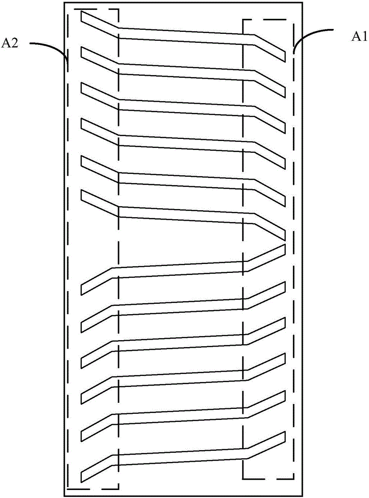
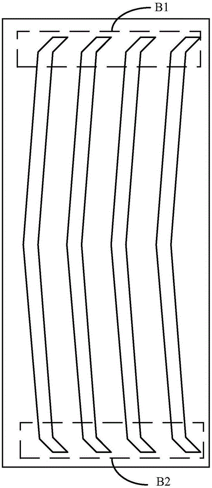
technical field [0001] The invention relates to the field of display technology, in particular to a liquid crystal display panel and a display device. Background technique [0002] In fringe field switching FFS display mode, in order to improve Trace Mura, the pixel electrode is designed to have a certain angle, such as the corner structure in the dotted frame area A1 and A2 shown in Figure 1(a). However, this design will cause the liquid crystal to not be completely deflected when the pixel is normally displayed, and there will be a certain dark area in the dotted frame area, which will eventually affect the liquid crystal light efficiency of the entire pixel structure and have a negative impact on the increase in product transmittance. [0003] In order to improve this defect of low light efficiency, the ordering of the pixel electrodes in the FFS display mode can be designed from horizontal to vertical, as shown in Figure 1(b), which is about to improve the extended area ...

Claims


Application Information

Patent Timeline
Patent Type & Authority Applications(China)
IPC IPC(8): G02F1/1362G02F1/1343
CPCG02F1/136286G02F1/134309G02F1/136209G02F1/136227
Inventor 刘晓那
Owner BOE TECH GRP CO LTD
Learn More