
Ceiling curtain with composite spring

A technology of composite springs and ceiling curtains, applied in the field of ceiling curtains, can solve the problems of stretching length limitation, large size and weight of springs, and inability to install, and achieves the effect of easy installation and reduced volume

Active Publication Date: 2016-10-12
王芳明
View PDF3 Cites 0 Cited by
  • Summary
  • Abstract
  • Description
  • Claims
  • Application Information

AI Technical Summary

Problems solved by technology

Reel-type ceiling blinds are widely used because they take up less space after being rolled. The structure of reel-type ceiling blinds generally includes a mounting shaft, a spring sleeved on the mounting shaft, a roller sleeved on the spring, and a roller wound on the roller. Cord, when the cord is stretched, the spring rotates and contracts to provide a tension force for the cord, so that the cord is in a straightened state. When the length of the cord is stretched, the greater the force required for spring contraction, so the diameter of the spring is required And the larger the wire diameter, and when the diameter and wire diameter of the spring increase, the expansion and contraction of the spring will decrease, resulting in that when the width of the cord is small and the stretched length is large, the length of the spring exceeds the cord Therefore, the stretching length of the curtain is limited by the width; further, the spring with large diameter and wire diameter has a large volume and weight, which is not easy to install and use

Method used


Image

  • Ceiling curtain with composite spring
  • Ceiling curtain with composite spring
  • Ceiling curtain with composite spring

Examples


Embodiment Construction

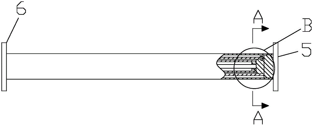
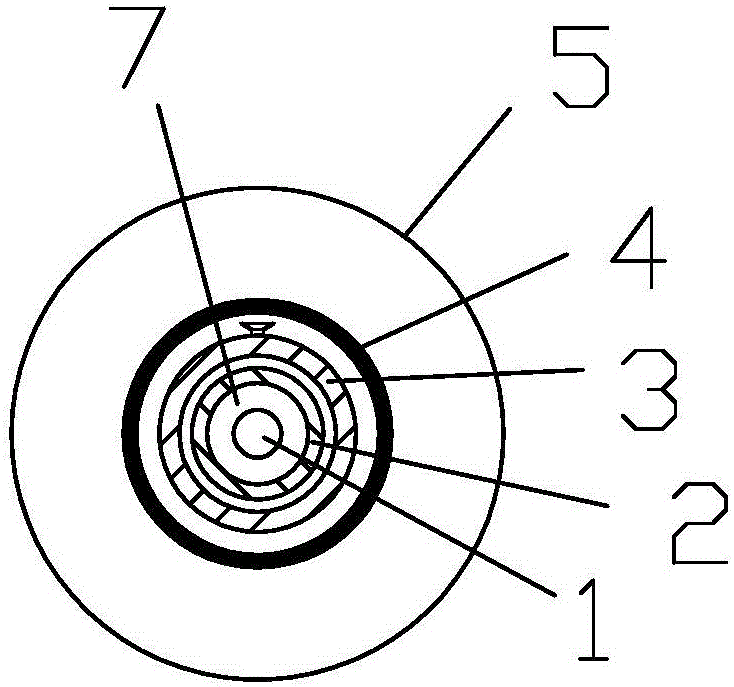
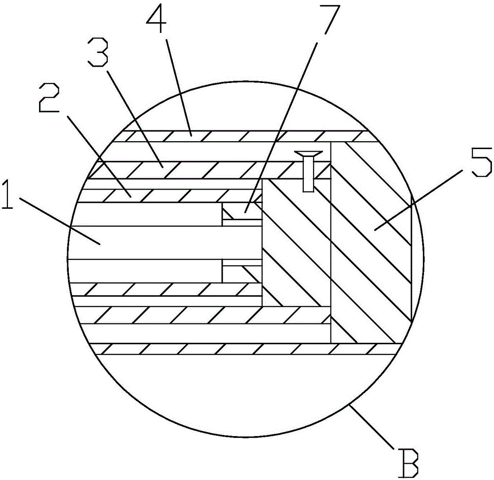
[0015] refer to Figure 1 to Figure 3 , a ceiling curtain with a composite spring provided in this embodiment includes a spring installation shaft 1, an inner spring 2 sleeved on the spring installation shaft 1, an outer spring 3 sleeved on the inner spring 2, an outer spring sleeved on the outer spring The roller 4 on the roller 3 and the curtain rolled on the roller 4, the two ends of the roller 4 are respectively connected with a rotating joint 5 and a fixed joint 6, the rotating joint 5 rotates with the roller 4, and the spring The two ends of the installation shaft 1, the inner spring 2, and the outer spring 3 are respectively connected with the rotary joint 5 and the fixed joint 6, and one end of the spring installation shaft 1 is fixedly connected with the fixed joint 6, and the other end is hinged with the rotary joint 5 to rotate The joint 5 rotates around the spring installation shaft 1 as an axis.

[0016] As a preferred embodiment, the two ends of the outer spring...


PUM


Abstract

The invention discloses a ceiling curtain with a composite spring. The ceiling curtain comprises a spring installing shaft, an inner spring, an outer spring, a roller tube and curtain cloth, wherein the inner spring is arranged on the spring installing shaft in a sleeving way; the outer spring is arranged on the inner spring in a sleeving way; the roller tube is arranged on the outer spring in a sleeving way; the curtain cloth is coiled on the roller tube; the two ends of the roller tube are respectively connected with a rotating connector and a fixed connector; the two ends of the spring installing shaft, the inner spring and the outer spring are respectively connected with the rotating connector and the fixed connector. The inner spring and the outer spring are arranged on the spring installing shaft, so that under the condition that the total elasticity of the inner spring and the outer spring is greater than or equal to that of a large-diameter spring, the higher expansion amount is realized; the adaptation to a longer curtain cloth can be realized; the size of the whole ceiling curtain can be reduced; the installation, the storage, the transportation and the like are convenient. Compared with a conventional ceiling curtain, the ceiling curtain has the advantage that under the conditions of the same curtain cloth width and the same size, the length of the curtain cloth is more than 30 percent longer than that of the conventional curtain cloth.

Description

technical field [0001] The invention relates to a ceiling curtain, in particular to a ceiling curtain with composite springs. Background technique [0002] Ceiling blinds are mainly used in sunshade systems for skylights. According to the operating principle, they can be divided into scroll type ceiling blinds, folding type ceiling blinds, blade flip type ceiling blinds, etc. Reel-type ceiling blinds are widely used because they take up less space after being rolled. The structure of reel-type ceiling blinds generally includes a mounting shaft, a spring sleeved on the mounting shaft, a roller sleeved on the spring, and a roller wound on the roller. Cord, when the cord is stretched, the spring rotates and contracts to provide a tension force for the cord, so that the cord is in a straightened state. When the length of the cord is stretched, the greater the force required for spring contraction, so the diameter of the spring is required And the larger the wire diameter, and w...

Claims


Application Information

Patent Timeline
IPC IPC(8): E06B9/44
CPCE06B9/44
Inventor 王芳明
Owner 王芳明
Learn More