
A built-in water separation power failure thermostat, temperature control method and water separation power failure sensor

A sensor and thermostat technology is applied in the field of built-in water-disconnecting and power-off thermostats, which can solve problems such as safety accidents, rust-prone joints, and failures, and achieve the effects of ensuring personal safety, uniform thermal conductivity, and stable performance.

Inactive Publication Date: 2017-06-16
CHINA UNIV OF MINING & TECH
View PDF6 Cites 0 Cited by
  • Summary
  • Abstract
  • Description
  • Claims
  • Application Information

AI Technical Summary

Problems solved by technology

Thermostat failure due to joints that are prone to rust in fish tank environments, or become easily covered with dirt
Under certain conditions, a weak current becomes a strong current, which may cause a safety accident
[0003] Many thermostats for heating fish tanks are also disclosed in the prior art, but there is a common defect in these thermostats: in the power-on process, when the thermostat breaks away from the water environment and enters the air environment, the thermostat at this time The temperature in the tank will rise in a straight line until the shell ruptures. When a rupture occurs, the fragments of the shell will easily splash on the body, causing great harm to the human body.

Method used


Image

  • A built-in water separation power failure thermostat, temperature control method and water separation power failure sensor
  • A built-in water separation power failure thermostat, temperature control method and water separation power failure sensor
  • A built-in water separation power failure thermostat, temperature control method and water separation power failure sensor

Examples


Embodiment Construction

[0024] The present invention will be further described through specific embodiments below in conjunction with the accompanying drawings.

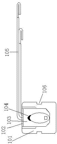
[0025] Such as figure 1 , figure 2 As shown, a water-disconnected power failure sensor includes a hollow cylindrical aluminum casing 101 with one side open. The size of the aluminum casing 101 is Φ6*7mm. There is a thermistor 102 inside the aluminum casing 101. 312-C8 resistor, two polyimide tubes 105 are connected to the thermistor 102, the sizes are 0.4*0.06*45mm and 0.4*0.06*35mm respectively, and the free ends of the two polyimide tubes 105 extend To the outside of the aluminum case 101, the gap between the thermistor 102 and the aluminum case 101 is filled with white high-temperature resin I103. The connection between the tube 105 and the thermistor 102 is coated with black resin II 104, which has a waterproof function. The outer peripheral surface of the aluminum casing 101 is provided with a circle of grooves 106 along the circum...


PUM


Abstract

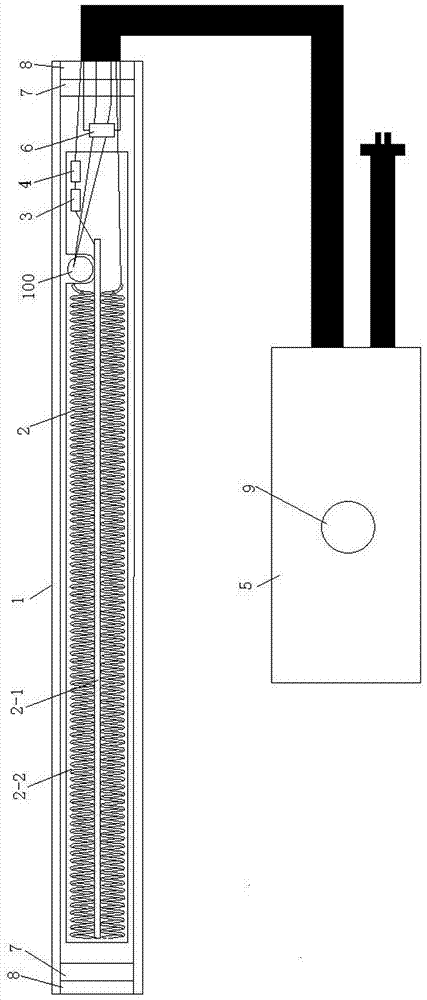
The invention discloses an internal-mounted water-leaving-power-off thermostat. The internal-mounted water-leaving-power-off thermostat comprises a quartz tube. A heating frame is arranged in the quartz tube, and comprises a cruciform mica frame and four heating wires, the four heating wires abut against right-angle seams of the cruciform mica frame respectively, two free ends of the four heating wires are reserved, the rest ends of the four heating wires are sequentially connected in series, any one of the two free ends is sequentially connected with a temperature control switch and a fuse to be connected to a controller through a wire, and the other one of the two free ends is connected to the controller through a wire; a water-leaving-power-off sensor is located in the quartz tube, abuts against the four heating wires, and is connected to the controller through a wire; a constant temperature sensor is connected to the controller through a wire. According to the internal-mounted water-leaving-power-off thermostat, power of the thermostat can be automatically cut under the condition of leaving water through the independent-research-and-development water-leaving-power-off sensor, the danger that under the condition of leaving water, as the temperature rapidly rises, the thermostat is burst is avoided, and the personal safety of a user is guaranteed.

Description

technical field [0001] The invention relates to heating device technology, in particular to a built-in water-disengaging power-off thermostat. Background technique [0002] At present, the thermostats on the market are all in the way of dealing with current contacts. Through the conduction of water, a weak voltage and current is passed between the two joints to identify the use environment of water or air. The thermostat fails due to the fact that the joints in the fish tank environment are prone to rust, or are easily covered with dirt. Under certain conditions, a weak current becomes a strong current, which may cause a safety accident. [0003] Also disclosed in the prior art are many thermostats for heating fish tanks, but these thermostats generally have a defect: in the process of power-on, when the thermostat breaks away from the water environment and enters the air environment, the thermostat at this time The temperature in the tank will rise in a straight line unti...

Claims


Application Information

Patent Timeline
Patent Type & Authority Patents(China)
IPC IPC(8): A01K63/06F24H9/20H05B1/02
CPCA01K63/065F24H9/2021H05B1/0202H05B1/0252
Inventor 朴春德
Owner CHINA UNIV OF MINING & TECH
Learn More