
A Relay Type Indoor Clock Time Calibration Method and Indoor Clock Time Calibration System

An internal clock and relay-type technology, applied in the field of clocks and watches, can solve problems such as messy wiring, difficult wiring, and affecting the cleanliness and aesthetics of the indoor environment, so as to improve the transmission distance, improve accuracy, and ensure cleanliness and beauty.

Inactive Publication Date: 2018-09-28
山东省北极星时间测量工程技术研究中心
View PDF5 Cites 0 Cited by
  • Summary
  • Abstract
  • Description
  • Claims
  • Application Information

AI Technical Summary

Problems solved by technology

[0003] Among them, the technical defect of GPS timing lies in that: the satellite navigation antenna needs to be erected outdoors and connected to the indoor clock through cables to transmit timing signals, resulting in messy indoor wiring;
[0004] The technical defect of radio wave timing lies in: my country has a vast territory, and the timing signal sent by the BPC low-frequency time code broadcasting station established in Shangqiu, Henan Province cannot cover all parts of the country, and the application range of radio wave timing technology is limited;
[0005] The defect of the timing technology of the master clock time synchronization system is that the system is a wired synchronous control system, and the time signal or timing signal adopts a wired transmission method, which not only makes indoor wiring difficult, but also affects the cleanliness and aesthetics of the indoor environment

Method used


Image

  • A Relay Type Indoor Clock Time Calibration Method and Indoor Clock Time Calibration System
  • A Relay Type Indoor Clock Time Calibration Method and Indoor Clock Time Calibration System
  • A Relay Type Indoor Clock Time Calibration Method and Indoor Clock Time Calibration System

Examples


Embodiment 1

[0050] This embodiment provides a relay-type indoor clock timing system, and the structure of the relay-type indoor clock timing system will be described in detail below:

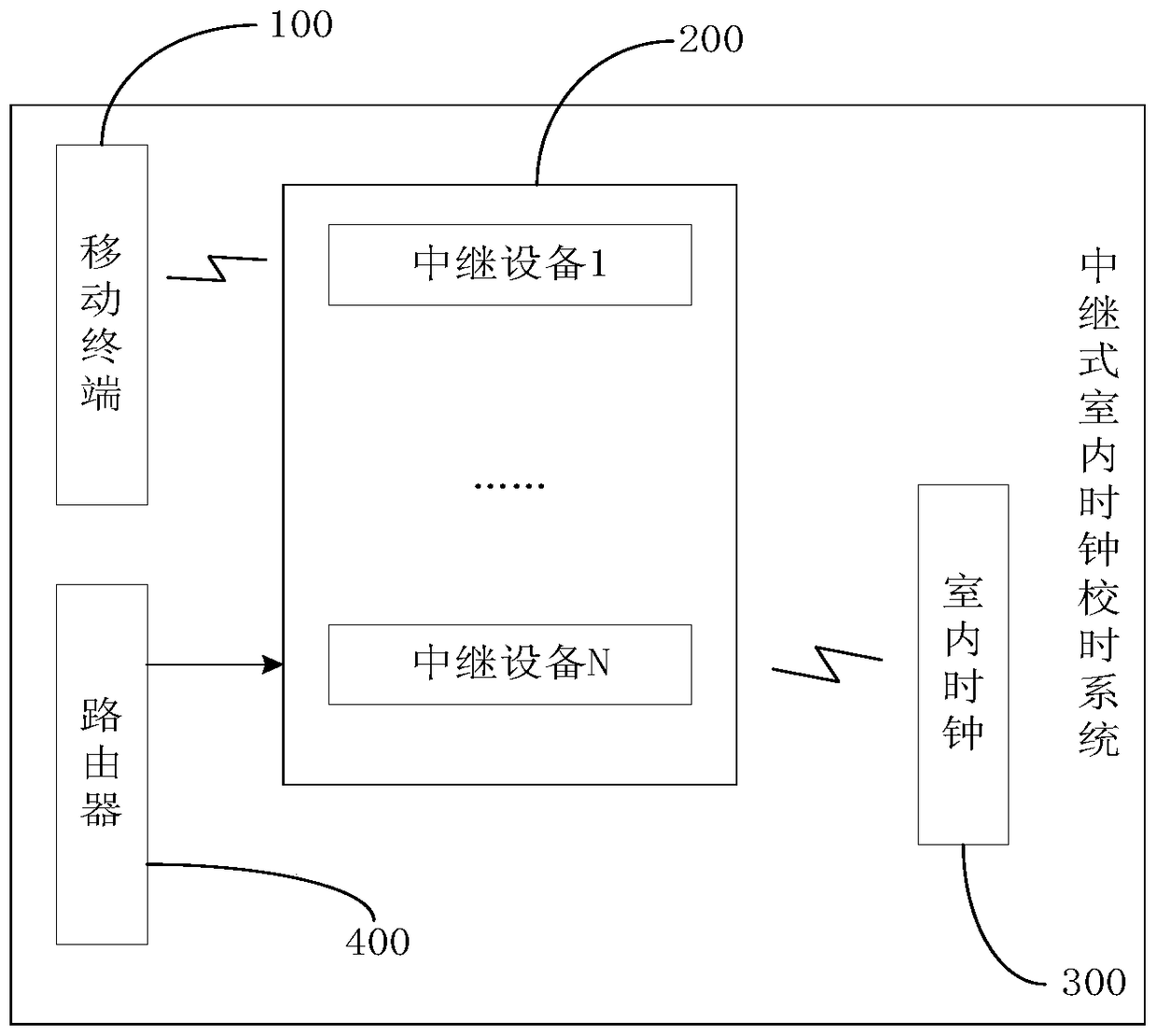
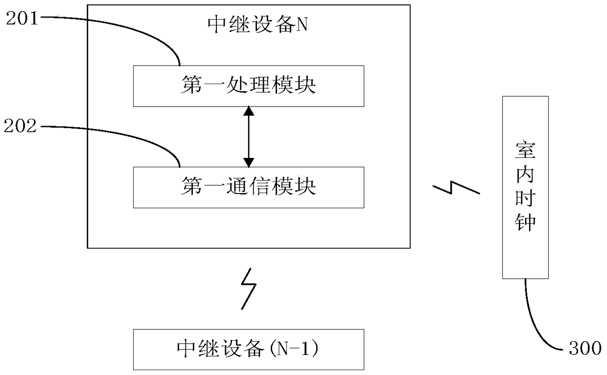
[0051] Such as figure 1 As shown, the relay-type indoor clock timing system of the present invention includes a mobile terminal 100, N relay devices 200 (wherein, N is a positive integer) located indoors and establishing wireless communication with the mobile terminal 100, and the N relay devices 200 The relay device 200 establishes the indoor clock 300 for wireless communication.

[0052] Wherein, the mobile terminal 100 is configured to acquire a network timing signal, and forward the network timing signal to one of the N relay devices 200 . The user can also control the work of the N relay devices 200 through the relay device 200 management APP installed and displayed under the UI interface of the mobile terminal 100 .

[0053] The indoor clock 300 is used to judge whether the travel time of the dial p...

Embodiment 2

[0068] This embodiment provides another relay type indoor clock timing system. The difference between the second embodiment and the first embodiment is reflected in: the way to obtain the network standard time is different. The way to obtain the network standard time in Embodiment 1 is: obtain the network time calibration signal through the mobile terminal 100, and forward the network time calibration signal to one of the relay devices 200 of the N relay devices 200; the network time calibration in Embodiment 2 The way to obtain the signal is: obtain the network standard time from the Internet through the router, and forward the network standard time to one of the relay devices 200 of the N relay devices 200 (such as Figure 4 shown).

Embodiment 3

[0070] This embodiment provides a relay type indoor clock time calibration method, the method includes the following processing steps:

[0071] Step 101, pre-setting the clock calibration trigger point (for example, 12:00:00) and the calibration duration of the indoor clock 300 (in a preferred embodiment of the present invention, the calibration duration is set to 10 minutes).

[0072] Step 102, the second processing module 302 of the indoor clock 300 judges whether the time of the clock has reached the set trigger point for clock time correction, and when the time of the clock reaches the trigger point for clock time correction, instruct the time correction module 303 to drive the clock movement 304 The transmission mechanism executes the corresponding action to suspend the movement of the hands of the dial, enter the time correction period, and start the timer 305 to time the time correction period.

[0073] Step 103 : Obtain the network time calibration time through N relay...


PUM


Abstract

The invention discloses a relay type indoor clock timing method and an indoor clock timing system. The system comprises an indoor clock and one or more relay devices arranged indoors. The indoor clock is used for determining to stop time travelling of a pointer at a dial plate temporarily to enter a timing period when clock traveling time (Tg) arrives at a clock timing trigger point location (Tc). Each relay device is used for obtaining a network timing signal, carrying out coding on the network timing signal, and forwarding a timing information code generated by the coding to the indoor clock or forwarding timing information code to other relay devices; and other relay devices transmit the timing information code to other relay devices. The indoor clock is used for receiving the timing information code, carrying out error prevention and misoperation prevention code checking on the timing information code, calculating an indoor clock travelling deviation (deltaT1) based on the timing information code, and driving a transmission mechanism in a clock movement to execute a corresponding action based on the indoor clock travelling deviation (deltaT1), so that the indoor clock traveling time (Tg) is corrected to be standard time (Ts).

Description

technical field [0001] The invention relates to the technical field of clocks and watches, and more specifically, relates to a relay-type indoor clock time-calibration method and an indoor clock time-calibration system. Background technique [0002] Since the frequency of the quartz crystal is easily affected by the ambient temperature, and the quartz crystal itself will age with time, the output frequency will drift, so the quartz clock will inevitably experience time errors as the service life increases. At present, in the watch industry, common indoor clock time calibration solutions include GPS time calibration, radio wave time calibration, and master clock time synchronization system time calibration. [0003] Among them, the technical defect of GPS timing lies in that: the satellite navigation antenna needs to be erected outdoors and connected to the indoor clock through cables to transmit timing signals, resulting in messy indoor wiring; [0004] The technical defect...

Claims


Application Information

Patent Timeline
Patent Type & Authority Patents(China)
IPC IPC(8): H04J3/06
Inventor 罗建毅
Owner 山东省北极星时间测量工程技术研究中心
Learn More