
A High Yield Flip Chip Power Amplifier and Its Application

A power amplifier and flip-chip technology, applied in power amplifiers, high-frequency amplifiers, amplifiers, etc., can solve the problem of uneven size of power amplifier cooling ground nodes, uneven stress between substrate and chip, and different sizes of flip-chip nodes. and other problems, to achieve the effect of reducing the use of flying leads, low cost and high integration

Active Publication Date: 2018-09-11
KUNSHAN CHENGTAI ELECTRIC
View PDF8 Cites 0 Cited by
  • Summary
  • Abstract
  • Description
  • Claims
  • Application Information

AI Technical Summary

Problems solved by technology

However, the disadvantage of this design scheme is that the size of other signal nodes and power amplifier heat dissipation ground nodes are very uneven, and the size of flip chip nodes is different, resulting in uneven stress on the substrate and chip after flipping. The most important nodes especially The ground node of each cascaded stage of the power amplifier is often transmitted to the semiconductor material of the chip due to excessive stress on the surface, resulting in a fracture in the semiconductor material layer of the chip, resulting in a decrease in product yield, and may even reduce the reliability of the product

Method used


Image

  • A High Yield Flip Chip Power Amplifier and Its Application
  • A High Yield Flip Chip Power Amplifier and Its Application
  • A High Yield Flip Chip Power Amplifier and Its Application

Examples


Embodiment Construction

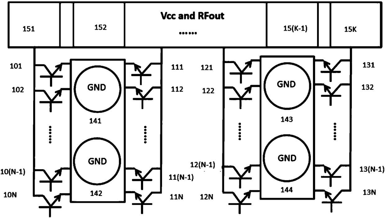
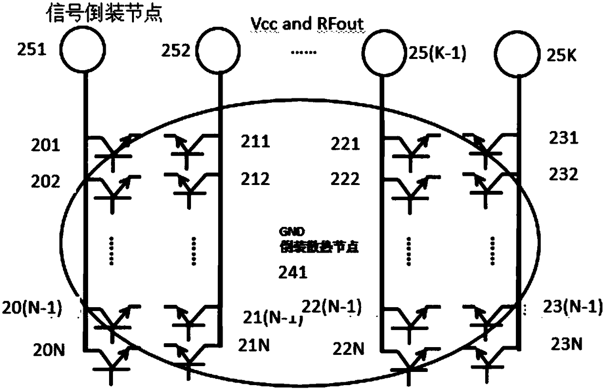
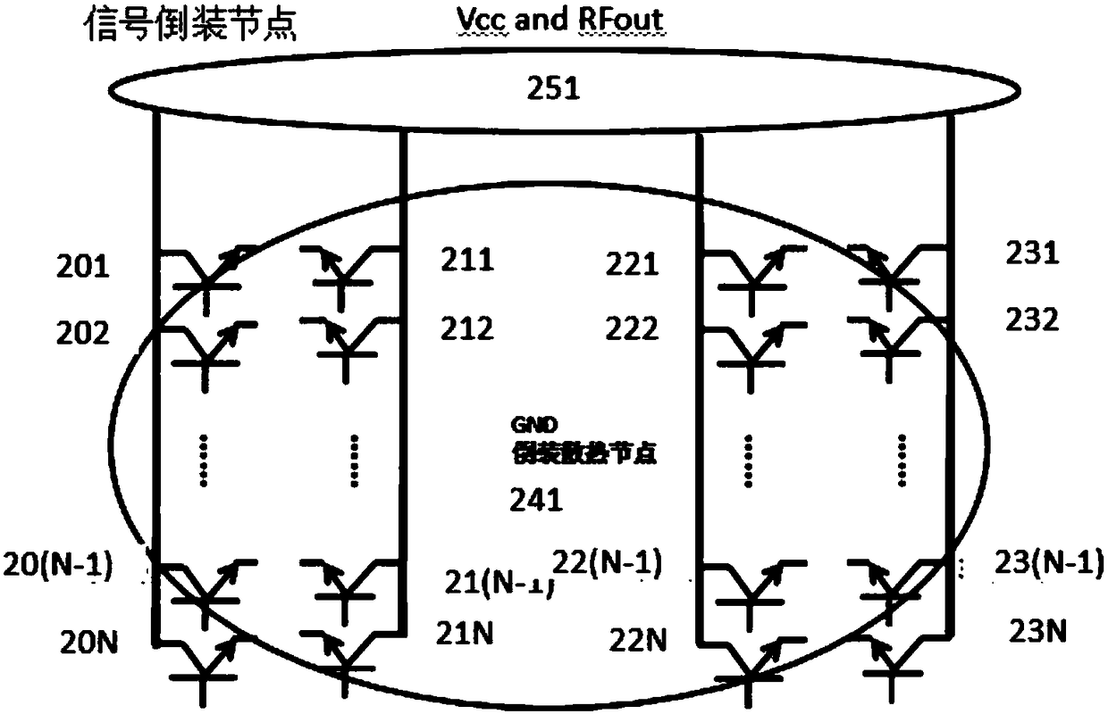
[0032] In this embodiment, a high-yield flip-chip power amplifier is connected in a cascaded manner by using at least two stages of amplifying circuits, and the power amplifier and the substrate are connected through the technology of flip-chip, and the stages in the amplifier are connected to each other. The grounding method of the combined amplifier circuit uses the high-density node flip-chip design method to achieve high-performance heat dissipation of the power amplifier. Because the power amplifier adopts flip-chip technology, the output stage circuit can be more effectively grounded for heat dissipation, thereby realizing a more efficient design solution for balanced heat dissipation, and improving the efficiency of the amplifier while maintaining the linearity of the amplifier. Specifically, the multimode power amplifier includes: an M-level cascaded amplifying circuit and an output matching circuit; the i-th cascaded amplifying circuit of the M-level cascaded amplifyin...


PUM


Abstract

The invention discloses a flip chip power amplifier with a high yield and an application thereof. The flip chip power amplifier is characterized in that NM amplification units connected in parallel of the M-th cascaded amplification circuit in the output stage of the power amplifier are four arrays arranged symmetrically; each array comprises NM / 4 amplification units connected in parallel; each amplification unit in each array is respectively connected with a corresponding ground wire GND flip chip node in a group of ground wires GND via the emitter or grid of the transistor by using the flip chip technology; and the amplification unit in each array is respectively connected with a corresponding power line VCC flip chip node in a group of power line VCC via the collector or grain of the transistor by using the flip chip technology. The flip chip power amplifier can use the clip chips with unified size to improve the density of grounded nodes of the power amplifier, thus achieving high yield and high reliability.

Description

technical field [0001] The invention relates to a radio frequency power amplifier, specifically a high-efficiency, high-yield, high-reliability power amplifier capable of balancing heat dissipation using a flip-chip process and its application. Background technique [0002] The radio frequency transmitting front-end module is a key component for radio frequency terminal devices to realize signal transmission. Currently, with the rapid growth of global wireless communication users and users' higher-end experience requirements for wireless communication, the market demand for wireless communication bandwidth is growing rapidly. In order to solve this market demand, more and more dedicated wireless communication frequency bands have been opened up around the world and are becoming more and more crowded. Modulation and demodulation methods with high frequency band utilization, such as: 3G Wideband Code Division Multiple Access (WCDMA), Band Code Division Multiple Access (Code D...

Claims


Application Information

Patent Timeline
Patent Type & Authority Patents(China)
IPC IPC(8): H03F1/02H03F1/30H03F1/32H03F3/19H03F3/213H03F3/24
CPCH03F1/0205H03F1/30H03F1/32H03F3/19H03F3/213H03F3/245
Inventor 马雷彭小滔蔡志强李磊
Owner KUNSHAN CHENGTAI ELECTRIC
Learn More