
A household DC microgrid voltage stabilizing circuit and control method

A technology of DC microgrid and voltage stabilizing circuit, which is applied in battery circuit devices, DC power supply parallel operation, circuit devices, etc., and can solve problems such as unstable output power, voltage instability, and bus voltage instability of wind/solar power generation units , achieve good DC terminal voltage stability control effect, avoid voltage and current impact, and switch control flexibly

Active Publication Date: 2019-04-30
CHINA THREE GORGES UNIV
View PDF6 Cites 0 Cited by
  • Summary
  • Abstract
  • Description
  • Claims
  • Application Information

AI Technical Summary

Problems solved by technology

On the one hand, the output power of the wind / solar power generation unit is unstable and uncertain, and the load difference between day and night is large, which is one of the main reasons for the instability of the bus voltage; on the other hand, the energy management capability of the controller Uncertainty changes lagging behind the output of the power supply unit, resulting in voltage instability
In order to achieve voltage stabilization, it is generally necessary to connect a large capacitor in parallel or increase the control frequency of the switch. The former increases the investment cost, and the latter increases the switching loss and generates high-frequency noise. The disadvantages are obvious.

Method used

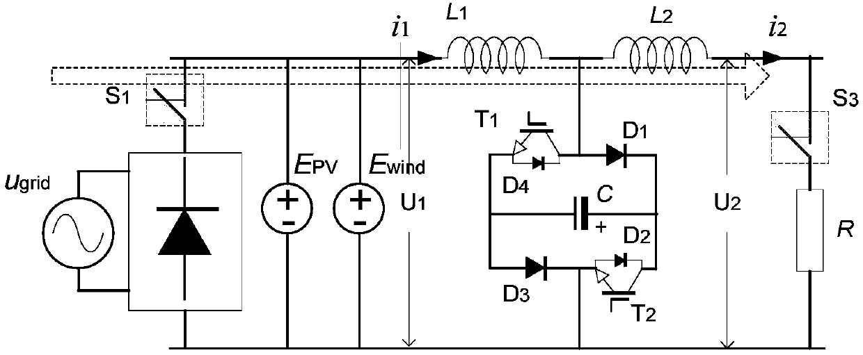
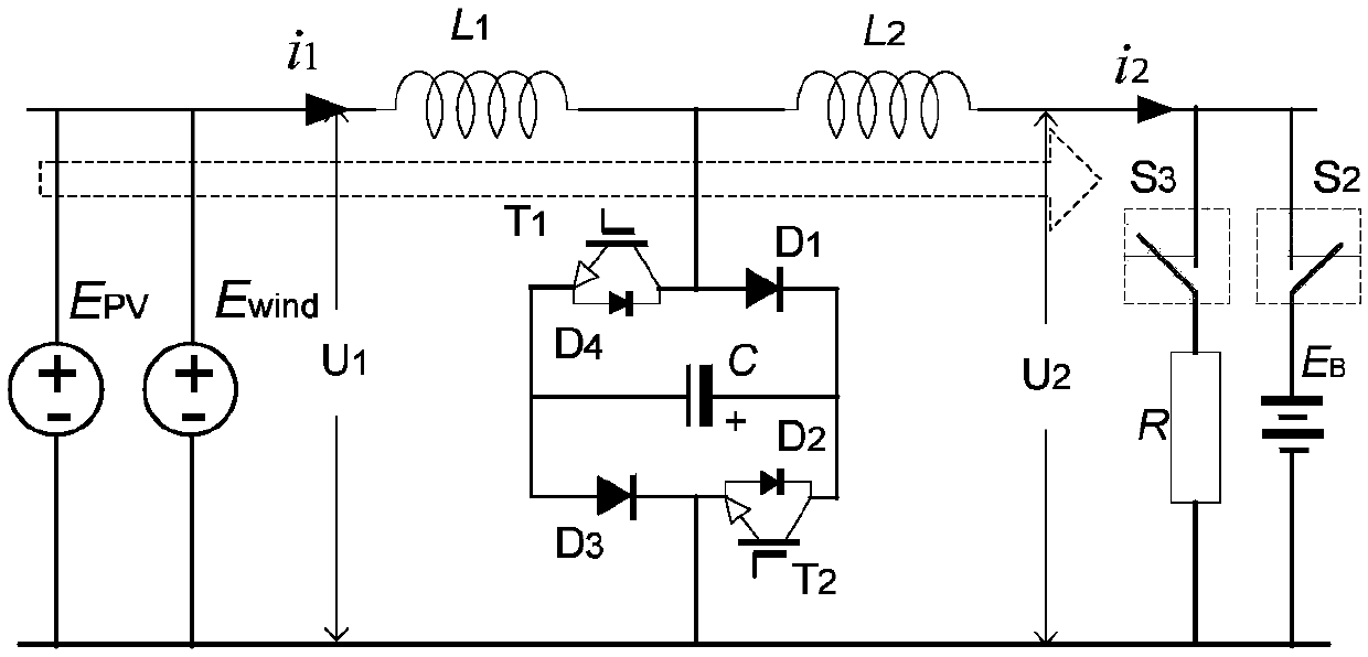

Image

  • A household DC microgrid voltage stabilizing circuit and control method
  • A household DC microgrid voltage stabilizing circuit and control method
  • A household DC microgrid voltage stabilizing circuit and control method

Examples


Embodiment Construction

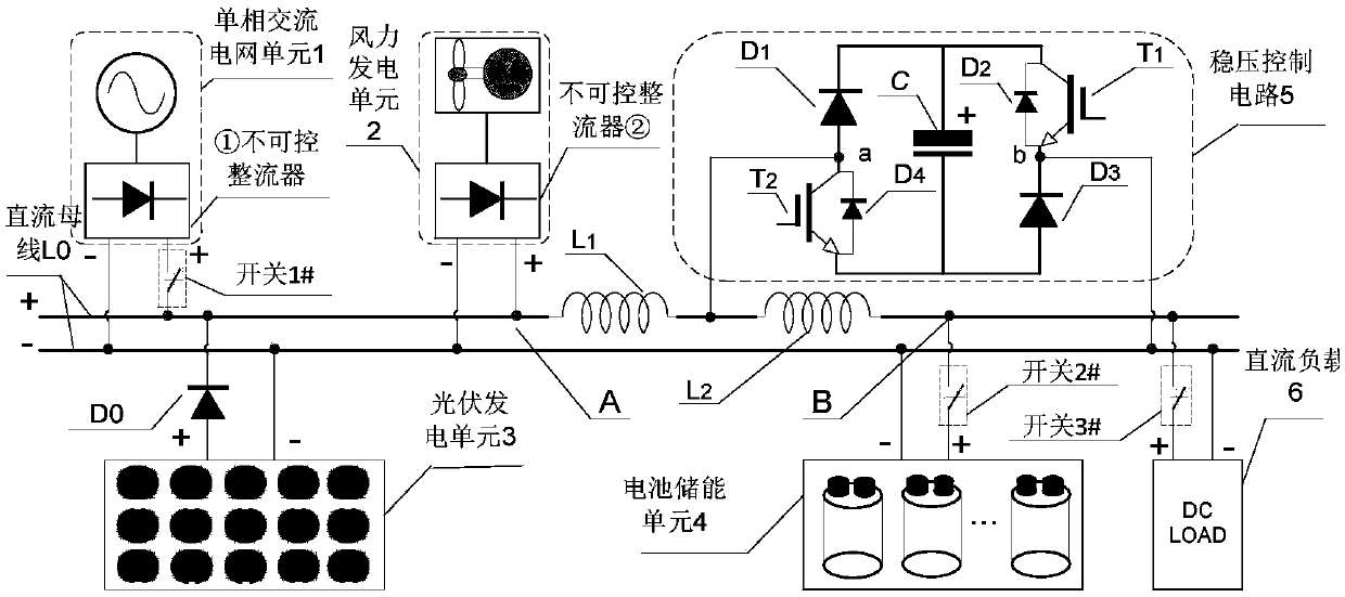
[0049] Such as figure 1 As shown, a household DC microgrid voltage stabilizing circuit includes a single-phase AC grid unit 1 , a wind power generation unit 2 , a photovoltaic power generation unit 3 , a battery energy storage unit 4 , a voltage stabilization control circuit 5 , and a DC load 6 .

[0050] The single-phase AC power grid unit 1 is connected to the first uncontrollable rectifier ①, the wind power generation unit 2 includes a wind power generator, and the wind power generator is connected to the second uncontrollable rectifier ②.

[0051] The photovoltaic power generation unit 3 includes photovoltaic panels.

[0052] The battery energy storage unit 4 adopts a battery pack.

[0053] The positive pole of the first uncontrolled rectifier ① is connected to one end of the first switch 1#, the other end of the first switch 1# is connected to the positive pole of the DC bus L0, and the negative pole of the first uncontrolled rectifier ① is connected to the negative pole...


PUM


Abstract

The invention discloses a household DC micro-power grid voltage stabilizing circuit and a control method. A single phase AC power grid unit is in connection to a first uncontrollable rectifier. A wind power generation unit is in connection to a second uncontrollable rectifier. The anode of the first uncontrollable rectifier is in connection to one end of a first switch. The other end of the first switch is in connection to the anode of a DC bus. The cathode of the first uncontrollable rectifier is in connection to the cathode of the DC bus. The anode and the cathode of the second uncontrollable rectifier are in respective connection to the anode and cathode of the DC bus. The anode of a photovoltaic power generation unit is in connection to the anode of a diode D0, and the cathode of the diode D0 is in connection to the anode of the DC bus. The cathode of the photovoltaic power generation unit is in connection to the cathode of the DC bus. A battery energy storage unit is in connection to the DC bus. A DC load is in connection to the DC bus. Connection points of a first reactor L1 and a second reactor L2 are in connection to an end of the voltage stabilization control circuit. A b end of the voltage stabilization circuit is in connection to the cathode of the DC bus. According to the invention, the voltage stabilizing circuit not only helps to reduce device cost, but also helps to reduce device loss and noise.

Description

technical field [0001] The invention relates to the field of DC micro-grids, in particular to a household DC micro-grid voltage stabilizing circuit and a control method. Background technique [0002] The development and utilization of renewable resources, such as wind energy and solar energy, play an important role in alleviating energy shortages and protecting the earth's environment. Household micro-grids are built according to the geographical location and climate characteristics of the house and local conditions. They can include distributed power sources such as wind power generation and solar power generation, and are equipped with energy storage batteries. As an important auxiliary method of distribution network power supply, it has a significant effect on improving the stability and reliability of household electricity consumption. At present, scholars at home and abroad have extensively studied microgrids, mainly including AC microgrids and DC microgrids. In compar...

Claims


Application Information

Patent Timeline
Patent Type & Authority Patents(China)
IPC IPC(8): H02J1/10H02J7/35H02J7/34H02M3/07H02M3/156
CPCH02J1/10H02J7/34H02J7/35H02M3/07H02M3/156Y02B10/10Y02E10/56Y02E10/76
Inventor 魏业文杨苗王辉程江洲黄悦华
Owner CHINA THREE GORGES UNIV
Learn More