
LED light source module and LED lamp

An LED light source and LED lamp technology, applied in the field of LED lighting, can solve the problems of high cost, low reliability, and short life of LED filament lamps, and achieve the effects of increasing production operability, simplifying production processes, and reducing production costs.

Inactive Publication Date: 2016-09-28
ZHEJIANG SHENGHUI LIGHTING
View PDF5 Cites 7 Cited by
  • Summary
  • Abstract
  • Description
  • Claims
  • Application Information

AI Technical Summary

Problems solved by technology

[0003] 1. At present, the structure and appearance of LED bulbs and traditional light sources do not match
[0004] 2. At present, LED bulbs have a smaller light angle than traditional light sources, and it is not easy to design a large angle
CN201410134869.5 discloses an LED light source module and a large-angle LED lamp. This patent effectively solves the problem of large-angle light emission, but there is a problem of inconvenient installation. In terms of electrical connection, slots need to be made on the top of the protrusion and the middle part of the LED light source module. Let the lead wire pass through the slot and then fix it with the middle part by soldering, the appearance is not beautiful, which increases the difficulty of assembly
[0005] 3. At present, although LED filament lamps achieve the above two points, the cost of LED filament lamps is high, the process is complicated, the reliability is low, the life is short, and the problem of heat dissipation is not easy to solve

Method used


Image

  • LED light source module and LED lamp
  • LED light source module and LED lamp
  • LED light source module and LED lamp

Examples


Embodiment

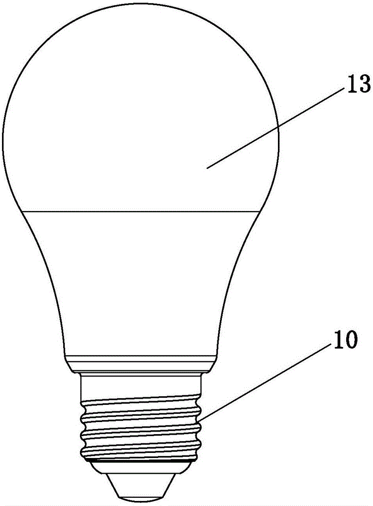
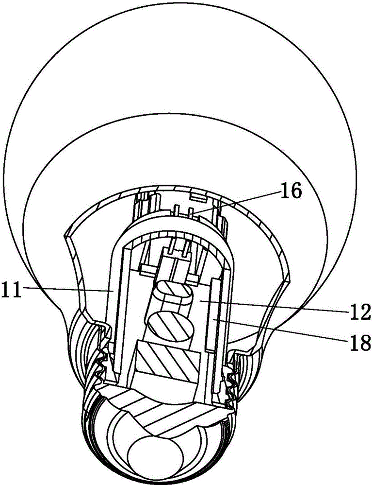
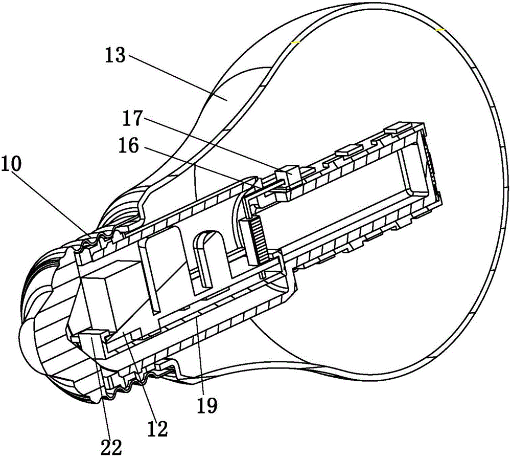
[0035] Embodiment: an LED light source module, such as Figure 5 ~ Figure 7 As shown, the module includes first and second LED light strips 1, 2. The first LED light strip 1 includes a first middle portion 3 and first wings symmetrically arranged on both sides of the first middle portion 3 and bent. The sheet 4 is provided with an LED chip 5 on the first fin 4; the second LED light strip 2 includes a second middle portion 6 and second fins 7 symmetrically arranged on both sides of the second middle portion 6 and bent. The second fin 7 is provided with an LED chip 5; the first LED light strip 1 and the second LED light strip 2 are crossed and the first and second intermediate parts 1 and 2 are stacked together.

[0036] The angle formed by the first fin 4 and the first intermediate portion 3 is 90 degrees; the angle formed by the second fin 7 and the second intermediate portion 6 is 90 degrees; in the uncovered first intermediate portion 3 or The surface of the two middle parts 6 ...


PUM


Abstract

The invention relates to an LED light source module and an LED lamp. The module comprises a first LED lamp band and a second LED lamp band. The first LED lamp band comprises a first middle part and bent first ribs symmetrically arranged on the two sides of the first middle part and provided with LED chips. The second LED lamp band comprises a second middle part and bent second ribs symmetrically arranged on the two sides of the second middle part and provided with LED chips. The first LED lamp band and the second LED lamp band are arranged in a crossed manner, and the first middle part and the second middle part are stacked together. The invention further provides the LED lamp based on the above light source module. According to the module, the first LED lamp band and the second LED lamp band are arranged in the crossed manner, the crossed positions are stacked together, electric conduction connection between metal is achieved through contact in crossed stacking, and additional circuit connection through a lead is not needed any more. Meanwhile, the first ribs and the second ribs are bent, a certain angle is kept between the first ribs and the first LED lamp band, a certain angle is kept between the second ribs and the second LED lamp band, and a large angle light emitting body is formed.

Description

Technical field [0001] The invention relates to the technical field of LED lighting, in particular to an LED light source module and an LED lamp. Background technique [0002] Some of the more mainstream LED bulb designs are as follows: [0003] 1. At present, the structure and appearance of LED bulbs are not consistent with traditional light sources. [0004] 2. At present, LED bulbs have a smaller light-emitting angle than traditional light sources, and large angles are not easy to design. CN201410134869.5 discloses an LED light source module and a large-angle LED lamp. This patent effectively solves the problem of large-angle light emission, but has the problem of inconvenience in installation. In terms of electrical connection, it is necessary to slot the raised top and the middle of the LED light source module. The lead wire is passed through the slot and then soldered to the middle part, which is not beautiful in appearance and increases the difficulty of assembly. [0005] 3....

Claims


Application Information

Patent Timeline
Patent Type & Authority Applications(China)
IPC IPC(8): F21K9/232F21K9/238F21K9/66F21V3/00F21V19/00F21V23/00F21V23/06F21V29/83F21Y115/10
CPCF21V29/83F21V3/00F21V19/003F21V23/006F21V23/06F21K9/238H05K1/0209H05K1/189H05K2201/056H05K2201/058H05K2201/066H05K2201/10106F21Y2107/30F21Y2107/60F21Y2107/70F21K9/232F21Y2115/10
Inventor 万叶华刘林章
Owner ZHEJIANG SHENGHUI LIGHTING
Learn More