Eureka AIR delivers breakthrough ideas for toughest innovation challenges, trusted by R&D personnel around the world.

Semi-contact type sealing ball valve

A sealed ball valve, semi-contact technology, used in shaft seals, valve details, valve devices, etc., can solve the problems of rapid response, spherical surface corrosion, single structure, etc., to ensure reliable sealing, increase the extrusion area, and extend the use. effect of life

Active Publication Date: 2016-09-28
KUSN WEISA VALVE
View PDF9 Cites 0 Cited by
  • Summary
  • Abstract
  • Description
  • Claims
  • Application Information

AI Technical Summary

Problems solved by technology

Compared with other valves that control the flow of pipeline media, the traditional soft-sealed floating ball valve has the inherent characteristics of ball valves. However, the traditional floating hard-sealed ball valve lacks quick response to on-site maintenance services due to its single structure, and especially in some easy-to-reach areas. Special working conditions where pitting corrosion and medium crystallization occur, such as the application of superheated steam pipelines to air exhaust, because the spherical surface directly faces the atmosphere, external debris such as mixed rain and snow fall here, due to the high position of the system, the spherical surface The temperature will reach more than 500 degrees. On the one hand, the debris will be heated and hardened and adhere to the surface of the ball. On the other hand, the frozen rain and snow liquid will cause pitting corrosion on the coating of the spherical surface. The traditional floating hard-sealed ball valve cannot satisfy customers. And market demand, which greatly limits the development of hard-sealed floating ball valves

Method used


Image

  • Semi-contact type sealing ball valve
  • Semi-contact type sealing ball valve
  • Semi-contact type sealing ball valve

Examples


Embodiment Construction

[0018] The present invention will be further described below in conjunction with the accompanying drawings.

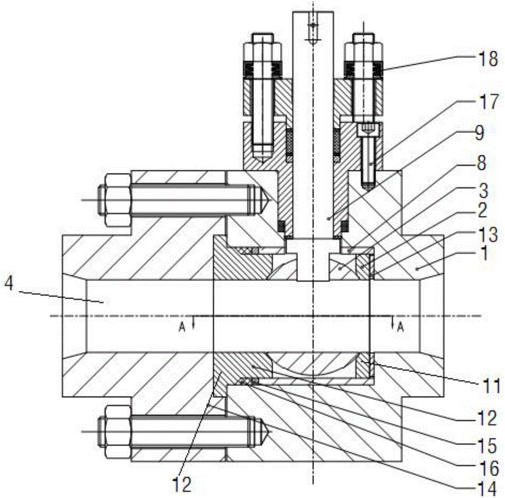
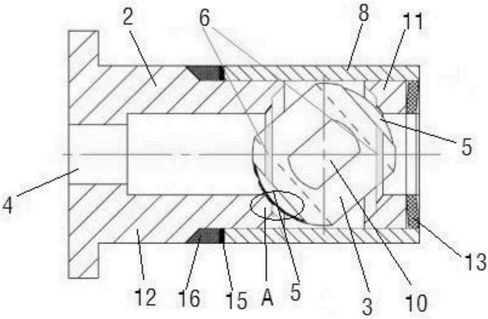
[0019] Such as Figure 1~Figure 3 As shown, a semi-contact sealed ball valve includes a valve body 1, a butterfly spring 13, an upstream supporting valve seat 11, a ball 3, a guide sleeve 8, a valve stem 9, a downstream valve seat 12, a gasket 15, and a wedge-shaped sealing ring 16. Valve cover 14, gland assembly 17, dynamic load spring 18. The valve body 1 is provided with a fluid channel 4, and the fluid channel 4 is provided with two opposite valve seats 2, and the ball 3 is arranged in a sealed manner between the two valve seats 2, and the valve body 1 The inner hole is provided with a guide sleeve 8, and the guide sleeve 8 is provided with a hole at the hole 9 of the valve stem. The bottom of the valve body 1 is provided with a butterfly spring 13, an upstream support valve seat 11, and a ball 3 in turn, and the other end of the guide sleeve 8 A gasket 15 and a ...


PUM


Abstract

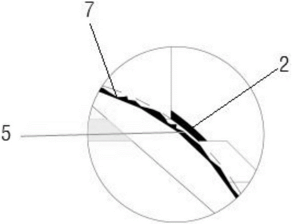
The invention discloses a semi-contact type sealing ball valve which comprises a valve body (1), valve seats (2) and a ball body (3). A fluid channel (4) is arranged in the valve body (1). The two opposite valve seats (2) are arranged on the fluid channel (4). The ball body (3) is arranged between the two valve seats (2) in a sealed manner. The surface of the ball body (3) is a non-continuous ball surface. The non-continuous ball surface comprises first ball surface bodies (5) located on the inner rings of sealing lines of the valve seats (2), and second ball surface bodies (6) making contact with the sealing lines of the valve seats (2) and having a sealing effect. The diameter of the first ball surface bodies (5) is smaller than the diameter of the second ball surface bodies (6). By means of the semi-contact type sealing ball valve, damage of corrosive media and media likely to be crystallized to the ball valve can be extremely effectively removed, and the service life of the valve is greatly prolonged.

Description

technical field [0001] The invention relates to a semi-contact sealed ball valve, in particular to a small-diameter metal hard-sealed floating ball valve, which belongs to the technical field of ball valves. Background technique [0002] As we all know, the main function of the ball valve is to cut off or connect the fluid channel in the pipeline. Its working principle is very simple. A certain torque is applied to the upper end of the stem with the help of a handle or other driving device and transmitted to the ball to make it rotate 90 ° (except for other special requirements), the through hole of the ball coincides with or is perpendicular to the center line of the valve body channel, and the ball valve completes the fully open or fully close action. The ball valve has developed into a main valve type due to its characteristics of small fluid resistance, fast switching, flat and smooth passage in the valve body, etc. It has been widely used in aerospace, petroleum, chemic...

Claims


Application Information

Patent Timeline
Patent Type & Authority Applications(China)
IPC IPC(8): F16K5/06F16K5/08F16K5/20F16K27/06F16K41/02
CPCF16K5/0605F16K5/0689F16K5/0694F16K5/201F16K27/067
Inventor 方月英周向青
Owner KUSN WEISA VALVE
Why Eureka
Eureka Blog
Learn More