
Electric gear and rack lifting mechanism of ocean platform

A lifting mechanism and offshore platform technology, applied in the field of offshore platforms, can solve the problems affecting the cooperation between the gearbox and the mounting frame, the torsional deformation of the bolts, and prolonging the braking time, so as to achieve easy installation and meshing, simple installation, and clean equipment Effect

Active Publication Date: 2016-09-28
WUHAN MARINE MACHINERY PLANT
View PDF6 Cites 8 Cited by
  • Summary
  • Abstract
  • Description
  • Claims
  • Application Information

AI Technical Summary

Problems solved by technology

[0004] The existing lifting mechanism is usually equipped with a hydraulic brake between the lifting gear box and the motor, but due to the delay in the response of the hydraulic system, this prolongs the braking time. In addition, both ends of the lifting gear shaft are mounted on the corresponding In the bearing sleeve, the lifting gear and the rack meshed with the lifting gear are arranged between the two bearing sleeves. This installation method is not only complicated, but also inconvenient to measure the installation and meshing conditions of the lifting gear and the rack. In addition, In the work of the lifting mechanism, due to the heavy load of the lifting mechanism, the gearbox will generate a large torque during work, and the gearbox is only connected to the mounting frame of the lifting mechanism through bolts, and the torque can only be transmitted to the mounting frame through bolts On the other hand, this will cause the bolts to twist and deform, which will affect the cooperation between the gearbox and the mounting frame, and then affect the normal operation of the entire offshore platform

Method used


Image

  • Electric gear and rack lifting mechanism of ocean platform
  • Electric gear and rack lifting mechanism of ocean platform
  • Electric gear and rack lifting mechanism of ocean platform

Examples


Embodiment Construction

[0024] In order to make the object, technical solution and advantages of the present invention clearer, the implementation manner of the present invention will be further described in detail below in conjunction with the accompanying drawings.

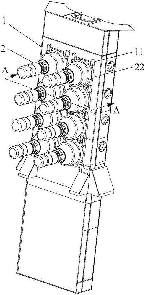
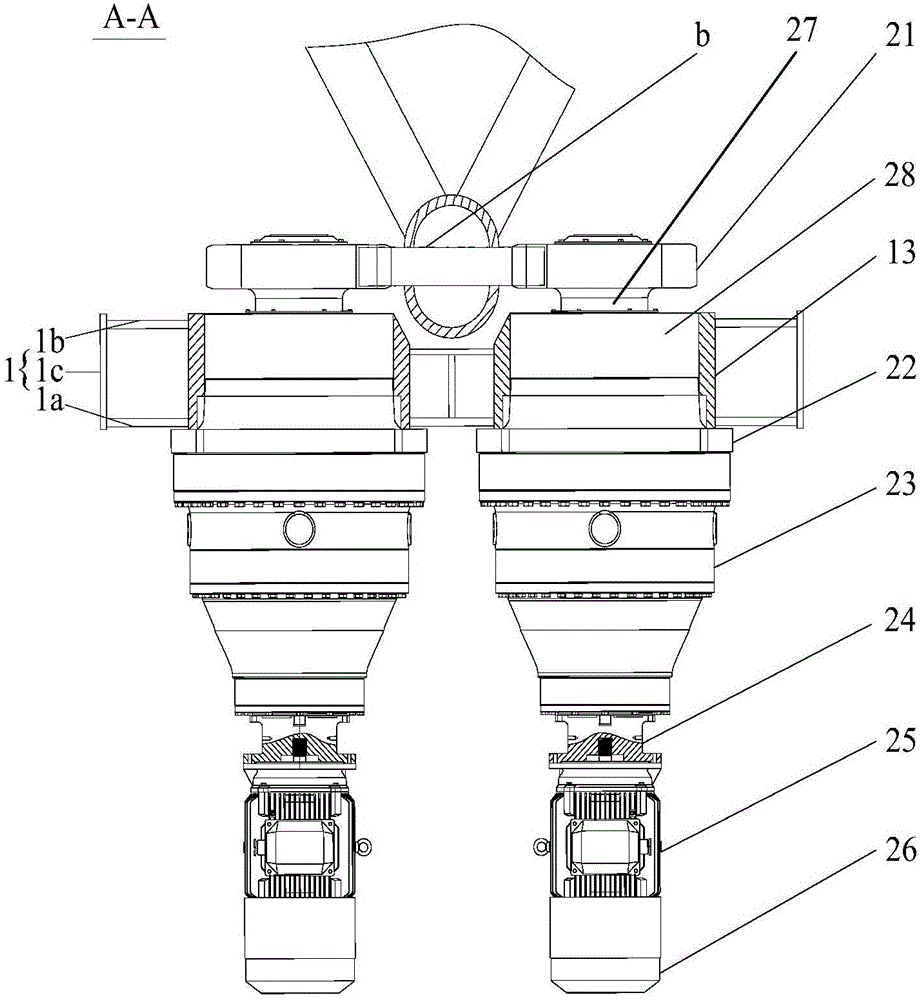
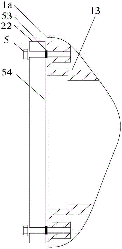
[0025] figure 1 It is a structural diagram of an electric rack and pinion lifting mechanism for an offshore platform provided by an embodiment of the present invention, as shown in figure 1 As shown, the lifting mechanism includes a mounting frame 1 installed on the legs of the offshore platform and a lifting unit 2 inserted on the mounting frame 1, figure 2 yes figure 1 A cross-sectional view along the A-A direction, such as figure 2 As shown, the lifting unit 2 includes a lifting gear shaft 27, a lifting gear box 23, a motor 25 and a first electromagnetic brake 26 arranged at the tail end of the motor 25, the lifting gear box 23 is connected with the mounting frame 1 through a mounting flange 22, and the lifting gear box The out...


PUM


Abstract

The invention discloses an electric gear and rack lifting mechanism of an ocean platform, and belongs to the field of ocean platforms. The lifting mechanism comprises a mounting frame and a lifting unit, wherein the lifting unit comprises a lifting gear shaft, a lifting gearbox, a motor and a first electromagnetic brake; a second electromagnetic brake is arranged between an input shaft of the lifting gearbox and an output shaft of the motor, so that the problem that brake time is too long due to adoption of a hydraulic brake is avoided; a mounting flange is fixed to the mounting frame by adopting a catch bolt, and a gasket is arranged on a shaft shoulder of the catch bolt, so that the mounting flange can shift on the catch bolt; the mounting flange is positioned by a torsion baffle block, so that torque is transmitted onto the mounting frame through the torsion baffle block, and therefore, the problem that the catch bolt is possibly damaged due to deformation of the mounting frame is avoided; and only one end of the lifting gear shaft is arranged in a bearing base, and therefore, the electric gear and rack lifting mechanism is simple to mount, and is convenient for measuring mounting and engaging occasions of gears and racks.

Description

technical field [0001] The invention relates to the field of ocean platforms, in particular to an electric rack and pinion lifting mechanism for an ocean platform. Background technique [0002] An offshore platform is a structure that provides production and living facilities for activities such as drilling, oil extraction, transportation, observation, navigation, and construction at sea. It usually consists of platform structures, pile legs, lifting mechanisms, living buildings, and helicopter decks. It is the basic equipment for developing offshore oil. [0003] As a key part of the offshore platform, the lifting mechanism is highly valued in the design, manufacture and use of the platform, and its performance directly affects the safety performance, performance and economy of the platform. The electric rack and pinion lifting mechanism has the advantages of fast lifting speed, large lifting capacity and high efficiency, and is widely used in offshore platforms. The elec...

Claims


Application Information

Patent Timeline
Patent Type & Authority Applications(China)
IPC IPC(8): E02B17/08
CPCE02B17/0818
Inventor 朱正都程文池赵世琏
Owner WUHAN MARINE MACHINERY PLANT
Learn More