
I2C transmission circuit and display device

A technology for transmission circuits and display devices, which is applied in static indicators, electrical digital data processing, optics, etc., and can solve problems such as device miswriting

Inactive Publication Date: 2016-09-21
TCL CHINA STAR OPTOELECTRONICS TECH CO LTD
View PDF11 Cites 17 Cited by
  • Summary
  • Abstract
  • Description
  • Claims
  • Application Information

AI Technical Summary

Problems solved by technology

[0005] The purpose of the present invention is to provide an I2C transmission circuit and a display device to solve the technical problem that it is easy to miswrite devices other than the target device during the I2C communication process

Method used


Image

  • I2C transmission circuit and display device
  • I2C transmission circuit and display device
  • I2C transmission circuit and display device

Examples


Embodiment 1

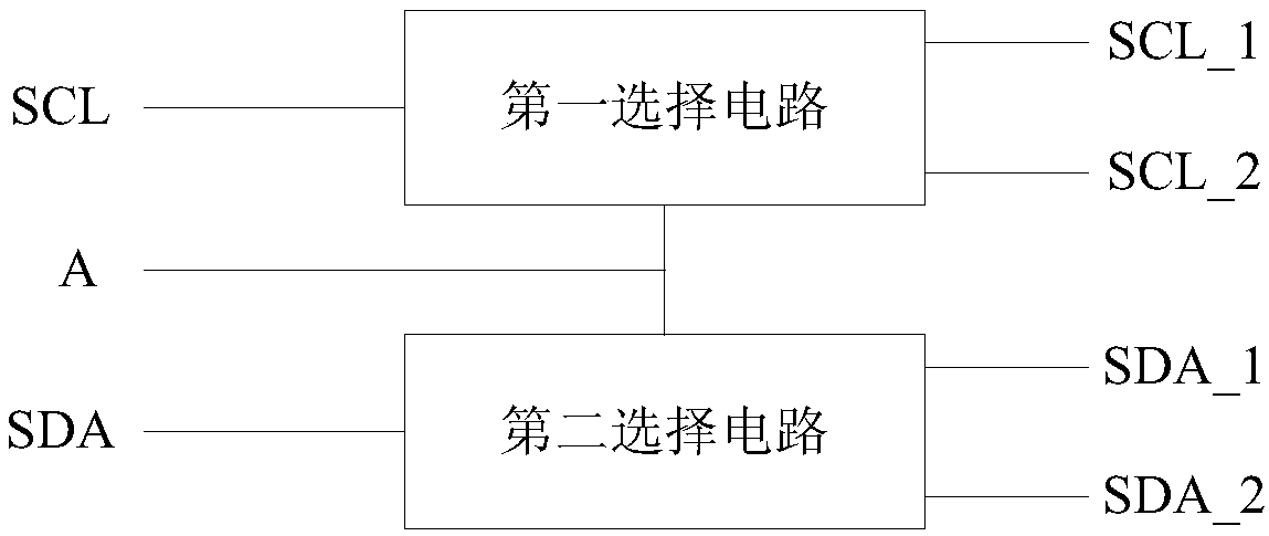
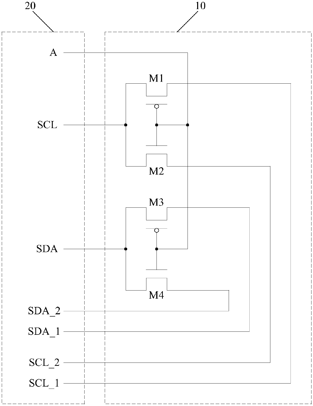
[0036] like figure 2 As shown, the embodiment of the present invention provides an I2C transmission circuit, including a first selection circuit, a second selection circuit and a selection signal line A, and the selection signal line A is connected to the control terminals of the first selection circuit and the second selection circuit.

[0037] In this embodiment, the input terminal of the first selection circuit is used to connect the serial clock line SCL, and the two output terminals SCL_1 and SCL_2 are respectively used to transmit the clock signal to the clock signal interface of the two devices; the input terminal of the second selection circuit The terminal is used to connect the serial data line SDA, and the two output terminals SDA_1 and SDA_2 are respectively used to transmit the data signal to the data signal interface of the two devices. Wherein, SCL_1 and SDA_1 are respectively connected to the clock data interface and data signal interface of the first device, ...

Embodiment 2

[0042] An embodiment of the present invention provides a display device, which may be a large display device such as a liquid crystal television, or a display device with a touch function such as a mobile phone or a tablet computer. The display device includes a driving circuit board and the I2C transmission circuit provided in Embodiment 1 above, and the I2C bus in the driving circuit board is connected to other devices through the I2C transmission circuit.

[0043] The display device provided by the embodiment of the present invention further includes an array substrate, a color filter substrate, and a liquid crystal layer filling the space between the array substrate and the color filter substrate. The I2C transmission circuit can be formed on the array substrate, so that the I2C transmission circuit can be formed synchronously with circuit structures such as thin film transistors in the display area through a photolithography process. The I2C transmission circuit in this e...


PUM


Abstract

The invention discloses an I2C transmission circuit and a display device, belongs to the technical field of display, and solves the technical problems in the I2C communication process that mistaken write-in of devices apart from a target device is liable to occur. The I2C transmission circuit comprises a first selection circuit, a second selection circuit and a selection signal line. The input end of the first selection circuit is used for connecting a serial clock line. The input end of the second selection circuit is used for connecting a serial data line. The selection signal line is connected with the control end of the first selection circuit and the second selection circuit. When the selection signal line is low-level, the input end of the first selection circuit and a first output end are conducted, and the input end of the second selection circuit and the first output end are conducted; and when the selection signal line is high-level, the input end of the first selection circuit and a second output end are conducted, the input end of the second selection circuit and the second output end are conducted. The I2C transmission circuit is suitable for a liquid crystal television set, a mobile phone, a tablet computer and other display devices.

Description

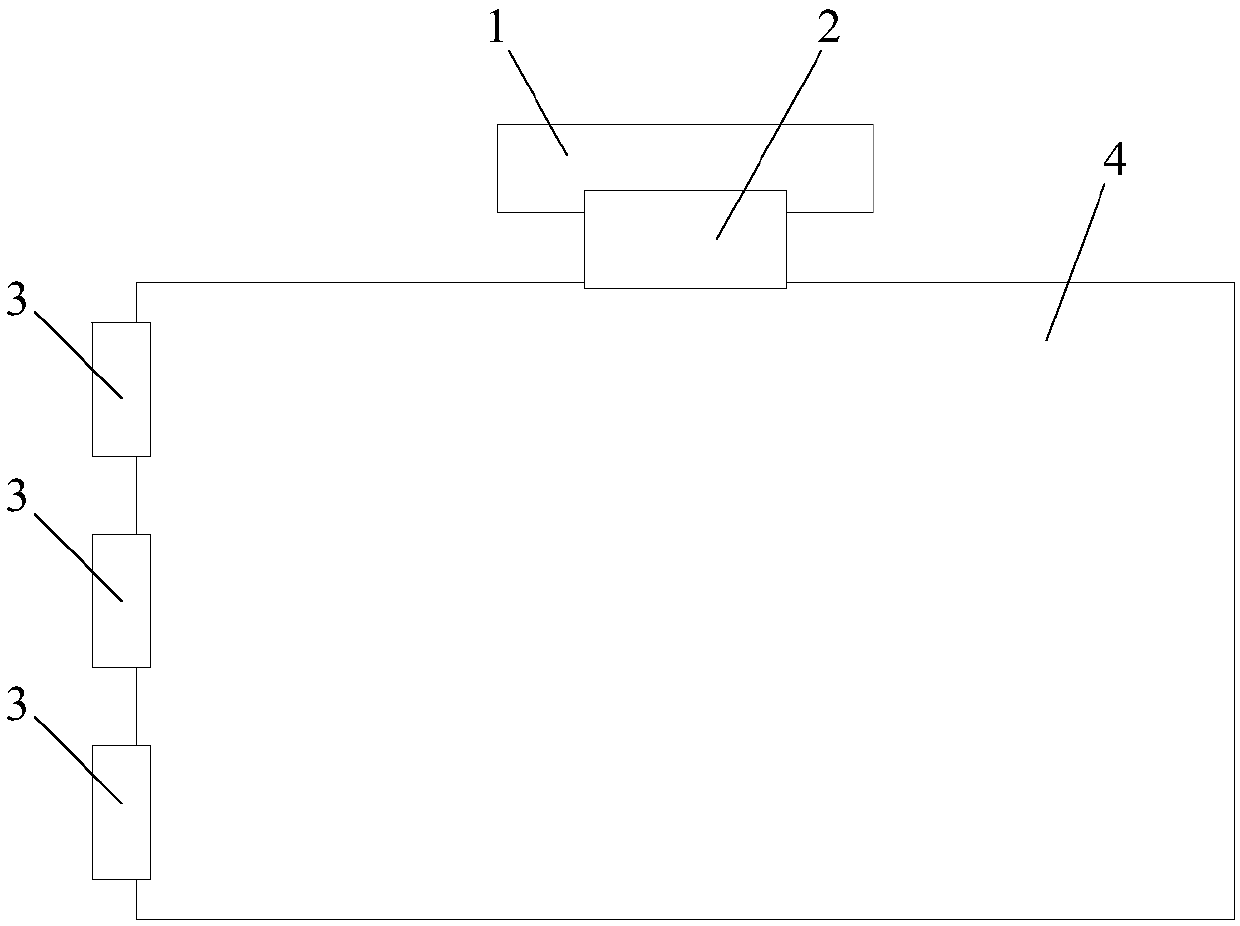
technical field [0001] The invention relates to the field of display technology, in particular to an I2C transmission circuit and a display device. Background technique [0002] With the development of display technologies, liquid crystal display screens have become the most common display devices. Among them, Thin Film Transistor Liquid Crystal Display (TFT-LCD for short) is one of the main varieties of current flat display devices, and has become an important display platform in modern IT and video products. [0003] The main driving principle of the liquid crystal display is that the system motherboard connects the red, green, blue compressed signals, control signals and driving signals to the connector on the driving circuit board through wires. like figure 1 As shown, after the data is processed by the timing controller (Timing Controller, referred to as T-CON) chip, the driving circuit board 1 passes through the data source-chip on film (referred to as S-COF) 2 and t...

Claims


Application Information

Patent Timeline
Patent Type & Authority Applications(China)
IPC IPC(8): G09G3/36
CPCG09G3/3611G09G3/3688G06F13/4072G06F13/4291G09G3/2096G09G3/3648G09G2300/0408G09G2330/08G02F1/133514G02F1/13452G02F1/1368G06F13/40G06F2213/0016
Inventor 黄笑宇
Owner TCL CHINA STAR OPTOELECTRONICS TECH CO LTD
Learn More