Heating furnace with coil pipes capable of being pulled away

A technology for heating furnaces and coils, applied to lighting and heating equipment, furnaces, tubular components, etc., can solve the problems of inability to guarantee the quality of repaired lining, poor construction environment and construction equipment, and inability to ensure thermal efficiency of cracking furnaces, etc., and meet production conditions And the effect of product quality improvement, guaranteed construction period, and simple structure

Active Publication Date: 2016-09-21
THE CHALLENGE PETROCHEM MACHINERY CORP
View PDF6 Cites 2 Cited by
  • Summary
  • Abstract
  • Description
  • Claims
  • Application Information

AI Technical Summary

Problems solved by technology

[0006] (2) The current construction method of heating furnace
Because the space inside the furnace wall is relatively narrow, and the installation site is constructed, the construction environment and construction equipment are relatively poor, the quality of the repaired lining cannot be guaranteed, and the high thermal efficiency and long service life of the cracking furnace cannot be guaranteed, making the convection section High maintenance costs and potential safety hazards

Method used


Image

  • Heating furnace with coil pipes capable of being pulled away
  • Heating furnace with coil pipes capable of being pulled away
  • Heating furnace with coil pipes capable of being pulled away

Examples


Embodiment 1

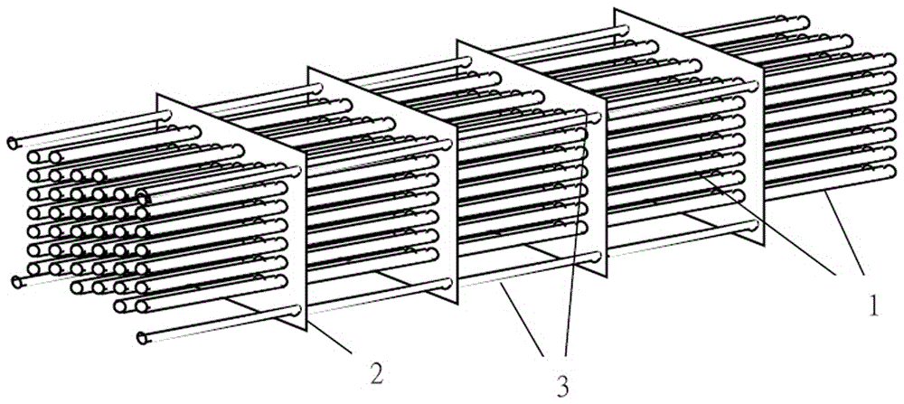
[0047] One of the heating furnaces with detachable coils in this embodiment, the heating furnace is assembled from several heat exchange coil modules, where the heat exchange coil modules refer to figure 1 and Figure 7 As shown, the heat exchange coil module includes furnace walls 16 on both sides, top beams 17, bottom beams 18, elbow boxes arranged at both ends of the furnace wall 16 and coil pipes arranged in the furnace wall 16. The coil pipes are composed of several The tube plate 2, furnace tube 1, elbow, flange short tube and header (not shown in the figure) are connected and assembled by welding. The furnace tube 1 is installed in the tube hole 13 on the tube plate, and the coil tube passes The legs on the plate 2 are supported on the lugs 15 inside the furnace wall 16, figure 1 The middle coil is a coil welded together, Figure 7 The middle coil is composed of three-component coils, and the coils can be withdrawn or pushed in whole or in part from the furnace wall 1...

Embodiment 2

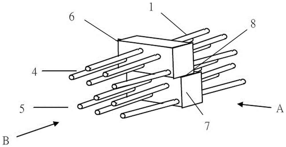
[0050] The second specific implementation mode of a heating furnace with detachable coil tubes in this embodiment, the main technical solution of this embodiment is the same as that of embodiment 1, and the features not explained in this embodiment are adopted in embodiment 1 explanation, and will not repeat them here. The difference between this embodiment and embodiment 1 is that, see figure 2 As shown, the coil is composed of two sets of coil stacks. The tube plate 6 of the first sub-coil 4 and the tube plate 7 of the second sub-coil 5 form a sliding pair 8, which is a sliding connection, and the coil can be integrated Withdraw or advance from the furnace wall, or part of the sub-coil can be withdrawn or advanced from the furnace wall. The coil is further divided into two sub-coils to reduce weight and facilitate pulling or pushing the coil from one end of the module.

Embodiment 3

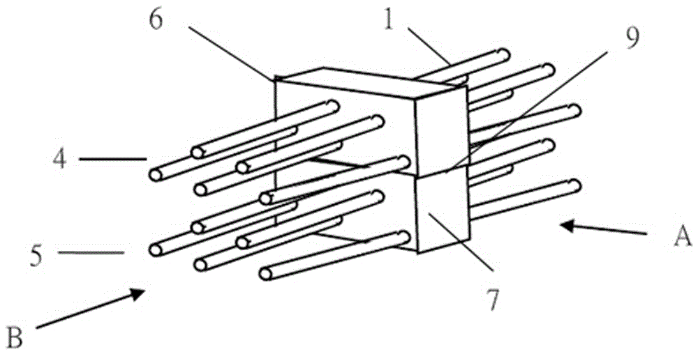
[0052] The third specific implementation of a heating furnace with detachable coil tubes in this embodiment, the main technical solution of this embodiment is the same as that of embodiment 1, and the features not explained in this embodiment are adopted in embodiment 1 explanation, and will not repeat them here. The difference between this embodiment and embodiment 1 is that, see image 3 As shown, the coil is composed of two sets of component coil stacks, and the contact surface between the tube sheets of the two component coils is a fixed surface 9, which is a fixed connection, and the coil can be pulled out or pushed in from the furnace wall as a whole. The coil is further divided into two sub-coils, which is convenient for transportation, reduces weight, and is convenient for pulling or pushing the coil from one end of the module.


PUM


Abstract

The invention discloses a heating furnace with coil pipes capable of being pulled away. The heating furnace is formed by assembling a plurality of heat exchange coil pipe modules; each heat exchange coil pipe module comprises furnace walls on the two sides, bend boxes arranged at the two ends of each furnace wall and the coil pipes arranged in the furnace walls; each coil pipe is formed by connecting and installing and welding of a pipe plate, a furnace pipe, a bend, a flange short pipe and a collection box; the pipe plates are borne on supporting lugs on the inner sides of the furnace walls, and the coil pipes can be drawn out from the furnace walls or pushed into the furnace walls; the coil pipes of the heat exchange pipe module at the lower portion of the heating furnace are changed to be assembled and welded on the job site of the furnace, and a new efficient and safe construction method of the building block modular type heating furnace is perfected; during construction, the upper modules are not affected by the delivery period of the furnace pipes of the modules on the lower portion, production conditions and product quality conditions are improved, the phenomenon that outdoor construction sites are affected by poor weather is avoided, and aerial work and crossing work at the job site are greatly reduced; and the individual coil pipes which are prone to being damaged are conveniently constructed, overhauled and replaced, the structure is simple, and the service life of the whole heating furnace can be prolonged.

Description

technical field [0001] The invention relates to the technical field of tubular heating furnaces in petroleum refining, petrochemical and other chemical industries, in particular to a heating furnace with detachable coiled tubes. Background technique [0002] (1) Structural design and function of traditional heating furnace [0003] Heating furnace is the leader in petrochemical industry, including atmospheric furnace, vacuum furnace, hydrogen production furnace, reforming furnace, coking furnace, reforming furnace and cracking furnace. The function of the tube heating furnace is to heat the medium (oil or gas) to the temperature required by the process. [0004] The four sides of the furnace body are surrounded by tall furnace walls. The furnace wall is made of I-shaped steel and other steel frames covered with welded steel plates. The steel plates are distributed with welded insulation nails, and heat insulation and wear-resistant materials are cast between the insulation ...

Claims


Application Information

Patent Timeline
IPC IPC(8): F28F9/02F28F1/14F27D1/00
CPCF27D1/00F28F1/14F28F9/02F28F2275/06
Inventor 陈孙艺
Owner THE CHALLENGE PETROCHEM MACHINERY CORP
Why Eureka
Try Eureka