
Device and method for protecting evaporation tank against large salt blocks

An evaporating tank and bulk technology, which is applied in the field of vacuum salt production or co-production of salt and nitrate, can solve problems such as the inability to prevent bulk salt production, and achieve the effects of prolonging a single operation cycle, promoting dissolution, and shortening rinse time.

Active Publication Date: 2016-09-21
HUNAN XIANGHENG SALT CHEM +1
View PDF6 Cites 0 Cited by
  • Summary
  • Abstract
  • Description
  • Claims
  • Application Information

AI Technical Summary

Problems solved by technology

The salt leg device of the salt making evaporation tank is mainly to promote the dissolution of bulk salt, and cannot prevent the production of bulk salt

Method used


Image

  • Device and method for protecting evaporation tank against large salt blocks
  • Device and method for protecting evaporation tank against large salt blocks
  • Device and method for protecting evaporation tank against large salt blocks

Examples


Embodiment 1

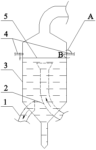
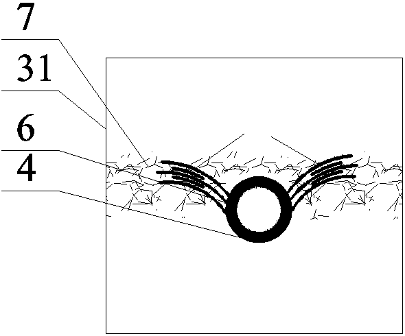
[0029] refer to figure 1 with figure 2 , a device for preventing the generation of bulk salt in the evaporating tank in this embodiment includes 4 flushing water pipes 4 that are evenly distributed on the tank wall 31 of the evaporating tank in a circumferential manner, and the distance between the flushing water pipes 4 and the liquid level of the evaporation chamber is more than 5 The vertical distance is 0.5m. One end of the flushing water pipe 4 is connected to the condensate pressurizer, and the other end passes through the tank wall 31 of the evaporation tank, and a flushing hole 6 is provided at the upper half of the end of the flushing water pipe 4 inside the tank wall. The central axis of the flushing hole 6 and the central horizontal section of the flushing water pipe 4 form an inclined angle of 30°.

[0030] The length of the flushing water pipe 4 located in the evaporation tank 3 is 0.05m.

[0031] The diameter of the flushing hole 6 is 20mm.

[0032] The flush...

Embodiment 2

[0035] refer to Figure 4 with Figure 5 , a device for preventing the formation of large lumps of salt in the evaporation tank of this embodiment, compared with Embodiment 1, there are the following differences:

[0036] The length of the flushing water pipe 4 located in the evaporation tank 3 is 0.08m.

[0037] The number of the flushing water pipes 4 is six.

[0038] The diameter of the flushing hole 6 is 15mm.

[0039] The flushing hole 6 is square.

[0040] The flushing water pipe 4 is provided with a solenoid valve 9 , and the solenoid valve 9 is connected with a time relay 8 .

Embodiment 3

[0042] A method for preventing block salt generation in an evaporating tank, comprising the following steps:

[0043] 1) Install at least four flushing water pipes 4 on the tank wall 31 of the evaporation tank above the liquid level 5 in the evaporation chamber, so that the flushing water pipes 4 are evenly distributed on the tank wall 31 of the evaporation tank in a circular manner, and the vertical distance from the liquid level 5 in the evaporation chamber ≤1m;

[0044]2) Set the interval time of the time relay 8 and the water flow time through the salt production control system, so that the solenoid valve 9 on the flushing water pipe 4 is opened at intervals, so that the flushing water pipe 4 is passed through water, and the tank wall 31 of the evaporation tank is flushed , when the water passing time reaches the set value, the solenoid valve 9 is closed, and the flushing water pipe 4 stops passing water, such as the device in embodiment 2; or, the water passing time of th...


PUM


Abstract

A device for protecting an evaporation tank against large salt blocks comprises at least four washing water pipes circumferentially and evenly distributed on the wall of the evaporation tank, the perpendicular distance, away from the liquid level of an evaporation chamber, of the washing water pipes is smaller than or equal to 1 m, one ends of the washing water pipes are connected with a condensate pressurizing device, the other ends of the washing water pipes penetrate through the wall of the evaporation tank, washing holes are formed in the upper half parts of the tail ends of the parts, located on the inner side of the wall of the evaporation tank, of the washing water pipes, and inclined included angles between the central axes of the washing holes and the center horizontal sections of the washing water pipes range from 15 degrees to 45 degrees. According to the device for protecting the evaporation tank against large salt blocks, no adhesion point is available for salt crystal particles on the wall of the evaporation tank, and the generation probability of large salt blocks is reduced; even if large salt blocks are formed on the original wall of the evaporation tank, large salt blocks can be efficiently washed by water columns generated by the washing water pipes, dissolving of large salt blocks is promoted, and the washing time of the evaporation tank is shortened.

Description

technical field [0001] The invention relates to a vacuum salt making or salt-nitrate cogeneration production device, in particular to a device and method for preventing the generation of bulk salt in an evaporation tank. Background technique [0002] At present, in the production of vacuum salt production and combined production of salt and nitrate, the internal reason for the frequent rinsing of the evaporator tank is that large pieces of salt are easy to form in the tank, and the falling off of large pieces of salt will cause the heating chamber to be blocked and affect the heat exchange effect; the piece of salt will enter the salt foot It may also block the salt discharge pipe, resulting in poor salt discharge; large pieces of salt directly fall into the circulation pipe, which will cause the current of the circulation pump to increase, increase the power consumption, and even cause the circulation pump motor to exceed the rated current and cause the equipment to trip. T...

Claims


Application Information

Patent Timeline
Patent Type & Authority Applications(China)
IPC IPC(8): B01D1/00B08B9/093B01D1/30
CPCB01D1/0082B01D1/30B08B9/0813
Inventor 曾华明骆成刘鑫
Owner HUNAN XIANGHENG SALT CHEM
Learn More