An external machine room cooling system
A heat dissipation system, external technology, applied in air conditioning systems, heating methods, household heating, etc., can solve the problems of built-in units occupying the space volume of the computer room, difficulty in meeting the business continuity of the data center, and strong dependence on heat generation. Achieve the effect of saving the internal space of the computer room, fast scalability, and good scalability
- Summary
- Abstract
- Description
- Claims
- Application Information
AI Technical Summary
Problems solved by technology
Method used
Image
Examples
Embodiment 1
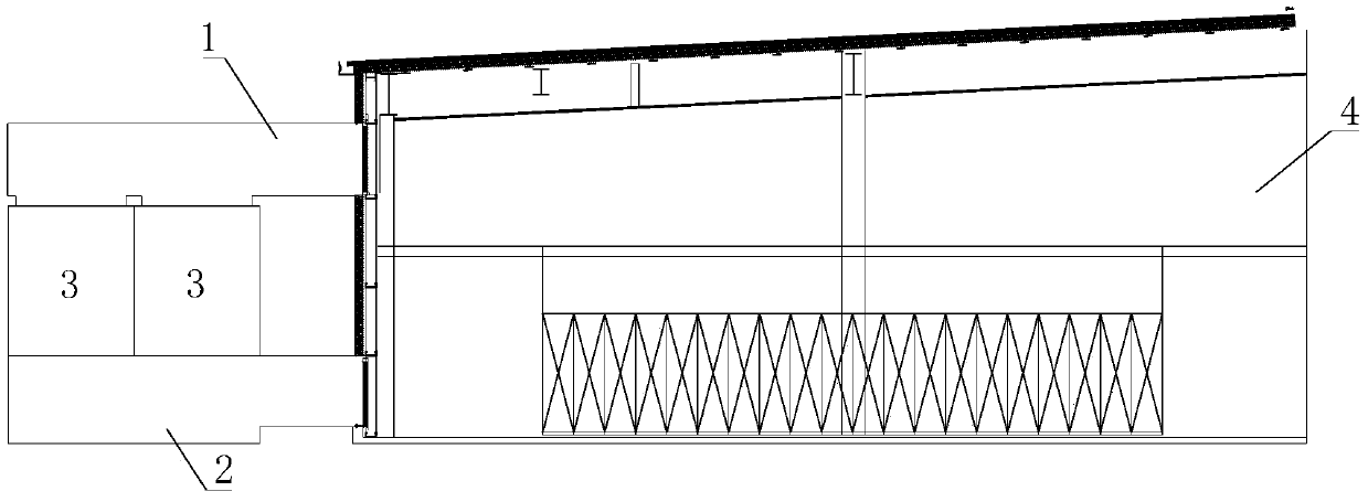
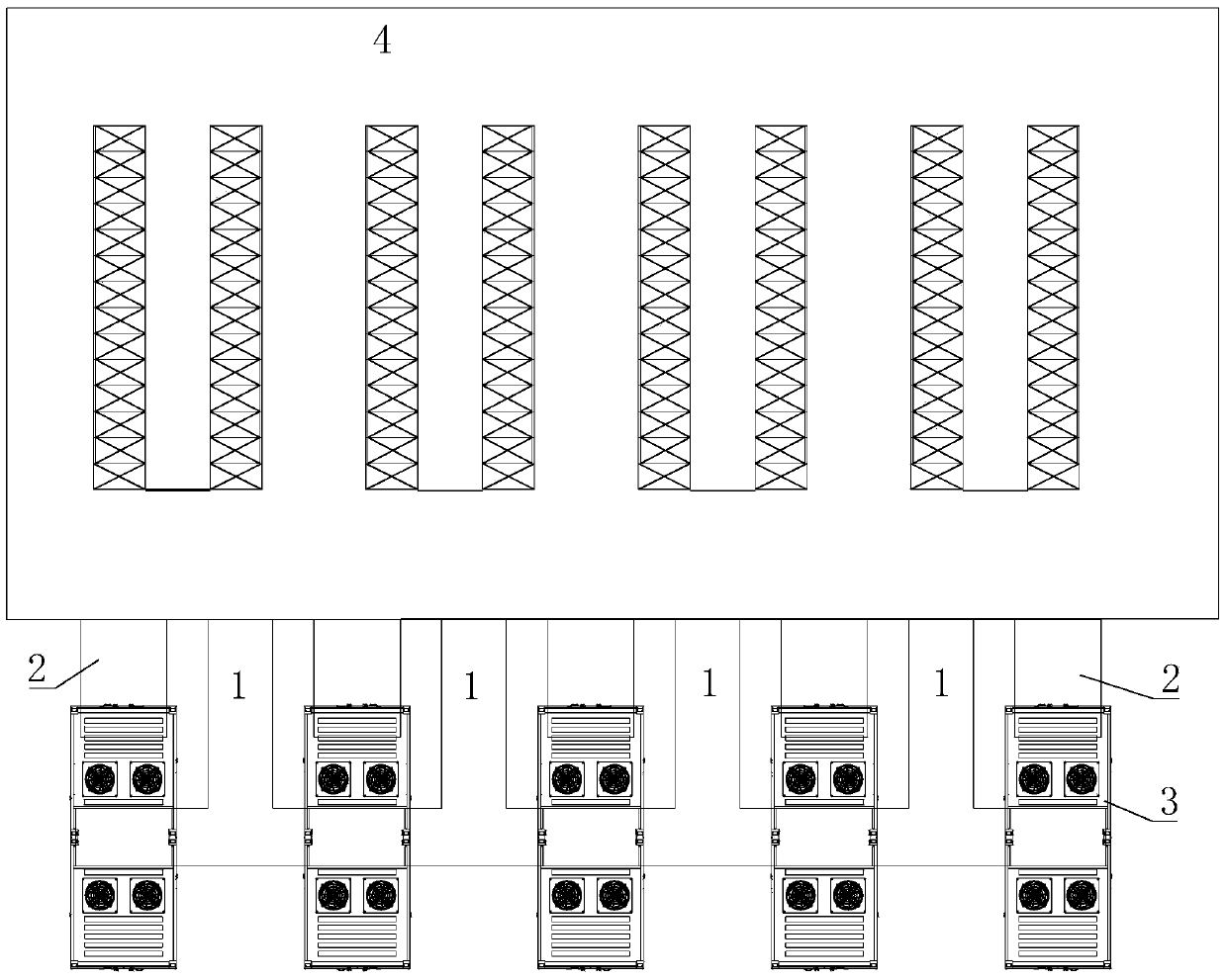
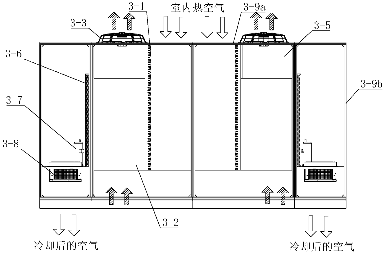
[0031] Such as figure 1 with figure 2 As shown, the cooling system of the machine room in this embodiment includes a return air duct 1 communicating with the machine room 4, an air supply duct 2 communicating with the machine room 4, and a heat dissipation unit 3 arranged outside the machine room. The air inlet connected to the return air duct 1 and the air supply outlet connected to the air supply duct 2, the cooling unit 3 also has an outdoor air inlet and an outdoor air outlet connected to the outdoor environment, and the cooling unit is connected between the outdoor air inlet and the outdoor air outlet. An outdoor air flow path is formed inside, and an indoor air flow path is formed in the cooling unit between the air inlet and the air supply port, and the outdoor air flow path and the indoor air flow path are isolated from each other. In this embodiment, the air supply duct 2 is located below the heat dissipation unit 3, and the return air duct 1 is located above the he...
Embodiment 2
[0039] Such as Image 6 As shown, the difference between this embodiment and Embodiment 1 is that this embodiment is a system in which the heat dissipation unit is applied to a closed cold aisle, and Embodiment 1 is a system in which a heat dissipation unit is applied to a closed hot aisle. The indoor air cooled by the heat dissipation unit 3 is discharged from the air outlet at the lower part of the heat dissipation unit 3 to the air supply duct 2, and then enters the common space isolated between the bottom of the server and the floor, and then distributed to each closed cold aisle.
Embodiment 3
[0041] Such as Figure 7 , Figure 8 and Figure 9 As shown, the difference between this embodiment and Embodiment 1 is that the return air duct 1 of Embodiment 1 is located above the heat dissipation unit 3, and the indoor hot air enters the heat dissipation unit from above the heat dissipation unit 3. The return air duct 1 of this embodiment Wind duct 1 is positioned at the side of heat dissipation unit 3, and indoor hot air enters in the heat dissipation unit from one side of heat dissipation unit 3, and the cooled indoor air is discharged into the air supply duct 2 from the air outlet at the bottom of heat dissipation unit. Cooling unit 3 can be arranged left and right ( Figure 9 ), and can also be arranged front and back ( Figure 10 ).
PUM
 Abstract
Description
Claims
Application Information
 - R&D
- Intellectual Property
- Life Sciences
- Materials
- Tech Scout
- Unparalleled Data Quality
- Higher Quality Content
- 60% Fewer Hallucinations
Browse by: Latest US Patents, China's latest patents, Technical Efficacy Thesaurus, Application Domain, Technology Topic, Popular Technical Reports.
© 2025 PatSnap. All rights reserved.Legal|Privacy policy|Modern Slavery Act Transparency Statement|Sitemap|About US| Contact US: help@patsnap.com


