Hot chamber die-casting die

A hot-chamber die-casting and mold-fixing technology, applied in the field of die-casting molds, can solve the problems of increasing the scrap rate of die-casting parts, poor molten metal flow, etc., and achieve the effect of improving production efficiency

Inactive Publication Date: 2016-09-14
CHONGQING YINGRUISHENG DIE CASTING
View PDF0 Cites 0 Cited by
  • Summary
  • Abstract
  • Description
  • Claims
  • Application Information

AI Technical Summary

Problems solved by technology

[0005] The present invention intends to provide a hot chamber die-casting mold to solve the problem that the molten metal cannot be well filled in the casting runner due to the poor flow of the molten metal, which in turn leads to an increase in the reject rate of the die-casting parts

Method used


Image

  • Hot chamber die-casting die

Examples


Embodiment Construction

[0013] The present invention will be described in further detail below by means of specific embodiments:

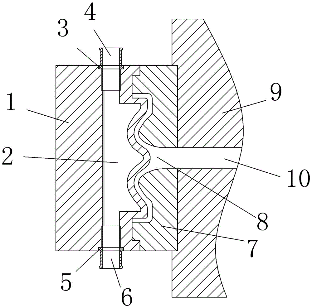
[0014] The reference signs in the drawings of the description include: movable mold 1, liquid flow channel 2, first waterproof gasket 3, liquid inlet pipe 4, second waterproof gasket 5, liquid outlet pipe 6, fixed mold 7, casting flow channel 8, fixed mold mounting plate 9, liquid inlet flow channel 10.

[0015] The embodiment is basically as attached figure 1 Shown: The hot chamber die-casting mold includes a moving mold 1, and a liquid flow channel 2 is opened on the moving mold 1. The liquid flow channel 2 is divided into a liquid inlet section, a middle section, and a liquid outlet section from top to bottom. Both the liquid section and the liquid outlet section are provided with threaded holes, and a first groove is opened on the upper side of the liquid inlet section, and a second groove is opened on the lower side of the liquid outlet section. The left side of the...


PUM


Abstract

The invention discloses a hot chamber die-casting die. The hot chamber die-casting die comprises a movable die body and a fixed die body. A fixed die installing plate is arranged at the position of the fixed die body. A liquid inlet runner is formed in the fixed die installing plate. A liquid runner is formed in the movable die body. The liquid runner comprises a liquid inlet section, a middle section and a liquid outlet section. The liquid inlet section of the liquid runner is in threaded connection with a liquid inlet pipe. The liquid outlet section of the liquid runner is in threaded connection with a liquid outlet pipe. The side, close to a casting runner, of the middle section of the liquid runner has the contour line the same as that that of the casting runner. According to the scheme, the liquid runner is formed in the movable die body, high-temperature liquid is injected into the liquid runner, molten metal in the casting runner always has good mobility through heat generated by the high-temperature liquid, and accordingly the problem that due to poor mobility of the molten metal, the casting runner cannot be well filled with the molten metal, and consequently the rejection rate of a die-casting fitting is increased is effectively solved.

Description

technical field [0001] The invention relates to a die-casting mold, in particular to a hot chamber die-casting mold. Background technique [0002] In the die casting forming process, the mold used to form the casting is called a die-casting mold, and the die-casting mold is generally composed of a moving mold and a fixed mold. [0003] The fixed mold is fixed on the fixed mold mounting plate of the die-casting machine. There is a sprue on the fixed mold that communicates with the nozzle or the pressure chamber. , when the movable mold and the fixed mold are closed, the mold cavity and the casting system will be formed. At this time, the liquid metal fills the mold cavity under high pressure; Casting rolls out. [0004] During the use of the currently used hot chamber die-casting mold, the molten metal enters the casting flow channel from the die-casting flow channel. During this process, the temperature of the molten metal will gradually drop, and the drop in the temperatu...

Claims


Application Information

Patent Timeline
Patent Type & Authority Applications(China)
IPC IPC(8): B22D17/22
CPCB22D17/22B22D17/2272
Inventor 曾令国
Owner CHONGQING YINGRUISHENG DIE CASTING
Why Eureka
Try Eureka