A metal sheet tensile and compressive experimental device in the form of a purely mechanical structure
What is Al technical title?
Al technical title is built by PatSnap Al team. It summarizes the technical point description of the patent document.
A kind of structural form, metal plate technology, applied in the field of material mechanics and performance research, can solve the problem that the fixture can not achieve axial load centering, can not compensate for the change of plate thickness, can not realize tension and compression experiments, etc., to save experimental costs, Simple structure and easy processing effect
Inactive Publication Date: 2019-04-12
DALIAN UNIV OF TECH
View PDF7 Cites 0 Cited by
Summary
Abstract
Description
Claims
Application Information
AI Technical Summary
This helps you quickly interpret patents by identifying the three key elements:
Problems solved by technology
Method used
Benefits of technology
Problems solved by technology
The fixtures used in the literature "Continuous, large strain, tension / compression testing of sheet material" and "A sheet tension / compression test forelevated temperature" can only prevent buckling of the measurement site, and additional hydraulic chucks and hydraulic lateral clamping are required device, the structure is relatively complex, and the equipment cost is relatively high
Moreover, due to the limitation of the fixture, only the experiment at a temperature below 400°C can be realized, and the tension-compression experiment at a higher temperature cannot be realized; the fixture used in the document "Elastic–plastic behavior of steel sheets under in-plane cyclic tension–compression at large strain" cannot Axial loading and centering can be achieved, and the thickness change of the plate cannot be compensated during the experiment, and the friction force of the experiment is relatively large
Moreover, the plastic strain ranges that the above-mentioned types of experimental fixtures can achieve are relatively small.
Method used
Image
Click on the blue label to locate the original text in one second.
Reading with bidirectional positioning of images and text.
Examples
Embodiment Construction
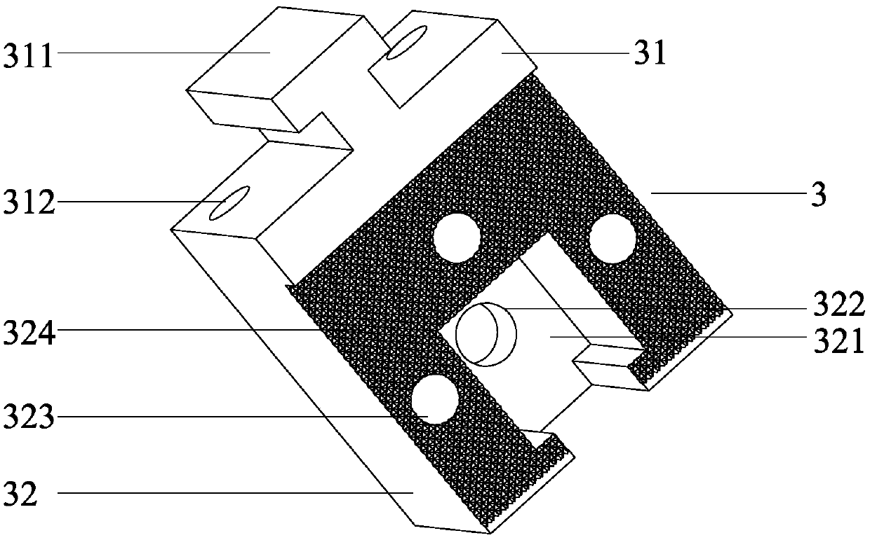
[0066] Such as Figure 11 , Figure 12 As shown, a metal sheet tension-compression test device in the form of a purely mechanical structure includes an upper connecting rod 1, a lock nut 2, an upper clamping block I3, an upper clamping block II4 matching the upper clamping block I3, a lateral Splint 5, lower clamping block I6, lower clamping block II7 matched with the lower clamping block I6, guide roller 8, fixture backing plate 9 and the lower connection fixed on the lower end of the fixture backing plate 9 and the table top of the testing machine Bottom plate 10 .
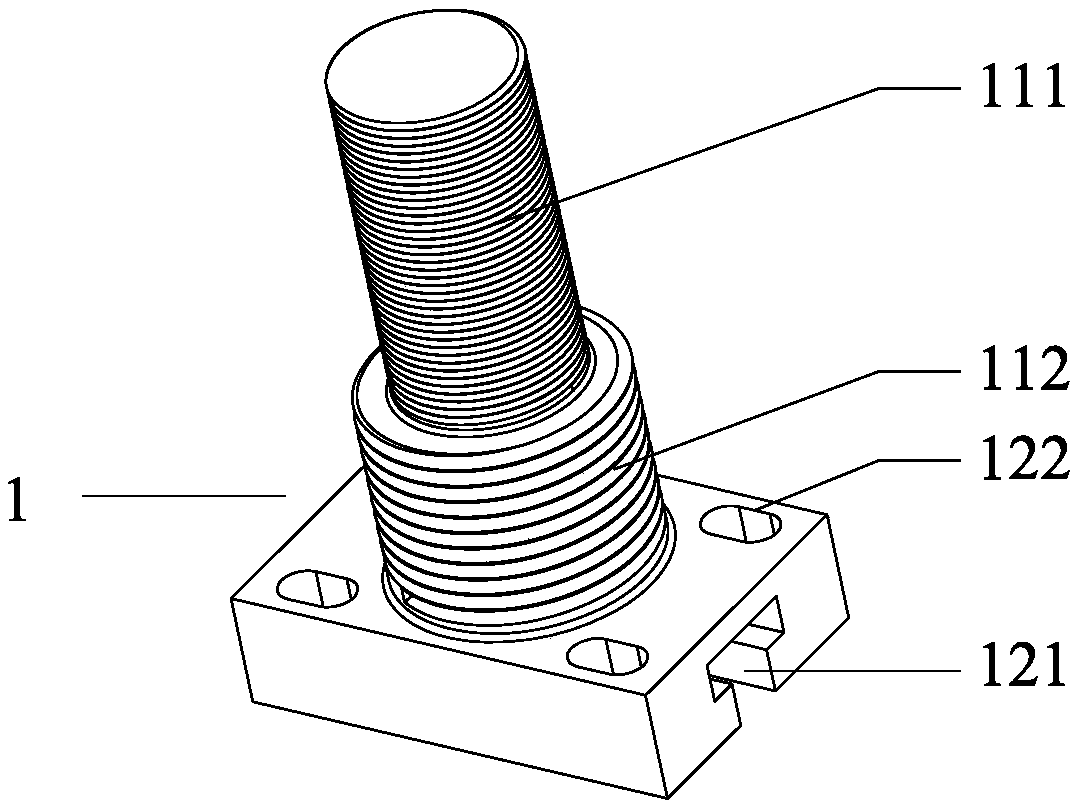
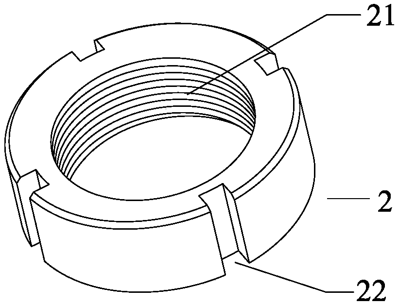
[0067] Such as figure 1 , 2 As shown, the upper connecting rod 1 includes an upper connecting part and a lower connecting part, and the upper connecting part is processed with a connecting thread 111 and a locking thread 112, and the connecting thread 111 is used to tighten and fix the upper connecting rod on the sensor of the testing machine , the locking thread 112 cooperates with the internal thread 21 of...
PUM
Abstract
The invention discloses a metal plate pulling-pressing experiment device in a pure mechanical structure form. The device comprises an upper connection rod, a locking nut, an upper clamp block (I), an upper clamp block (II), a lateral clamping plate, a lower clamp block (I), a lower clamp block (II), guide rollers, a clamp base plate, and a lower connection base plate, and is characterized in that two sides of a test piece are clamped by the lateral clamping plate, the upper end of the test piece is clamped by the upper clamp block (I) and the upper clamp block (II), then the upper clamp block (I) and the upper clamp block (II) are connected by the upper connection rod, through the locking nut, the upper connection rod is locked on a sensor of a tensile test machine, two side of the lower end of the test piece are provided with a guide roller respectively, the lower end of the test piece is clamped by the lower clamp block (I) and the lower clamp block (II), and then the lower clamp block (I) and the lower clamp block (II) are fixed by the clamp base plate. Through simple mechanical principle and mould technology, pricy hydraulic equipment and air pressure equipment are not needed, the structure is simple, the processing is easy, the experiment cost is saved, the operation is convenient, and the experiment results are precise.
Description
technical field [0001] The invention relates to the technical field of material mechanics and performance research, in particular to a metal sheet tension and compression experimental device in the form of a purely mechanical structure. Background technique [0002] In the field of sheet metal forming, the experimental methods used to study the properties of the sheet and check whether the sheet meets the specified standards mainly include tensile, shrinkage, fatigue, and creep experiments. Using the data obtained from the experiment, the stress-strain relationship, Bauschinger effect, fatigue strength, and basic elastic limit, elongation, elastic modulus, reduction of area, strength and other performance indicators of the material can be obtained. The mechanical properties and characteristics of the plates obtained from the above experiments are extremely important in guiding subsequent related experiments and actual production, and all the above experiments can be carried ...
Claims
Application Information
Patent Timeline
Application Date:The date an application was filed.
Publication Date:The date a patent or application was officially published.
First Publication Date:The earliest publication date of a patent with the same application number.
Issue Date:Publication date of the patent grant document.
PCT Entry Date:The Entry date of PCT National Phase.
Estimated Expiry Date:The statutory expiry date of a patent right according to the Patent Law, and it is the longest term of protection that the patent right can achieve without the termination of the patent right due to other reasons(Term extension factor has been taken into account ).
Invalid Date:Actual expiry date is based on effective date or publication date of legal transaction data of invalid patent.