Forced seal ball valve

A technology of forced sealing and ball valves, applied in the direction of valve devices, cocks including cut-off devices, engine components, etc., can solve the problems of large structure and volume, insufficient normal sealing force of valve seats, and the influence of turbulent flow on valve ball components, etc. , to achieve the effect of smooth and reliable transmission, rapid switching action, uniform and reliable cohesion force of forced sealing

Active Publication Date: 2016-09-07
刘晓琦
View PDF10 Cites 27 Cited by
  • Summary
  • Abstract
  • Description
  • Claims
  • Application Information

AI Technical Summary

Problems solved by technology

[0021] In order to overcome the relative sliding friction in the last stage of the sealing stroke existing in various forced sealing ball valves, the normal sealing force of the valve seat is insufficient, the structure and volume are huge, some designs require the use of hydraulic systems, and some designs exist when the valve is open. The valve ball assembly is affected by turbulent flow and other problems. The present invention satisfactorily solves these problems by starting from the basic structure for realizing sealing.

Method used


Image

  • Forced seal ball valve
  • Forced seal ball valve
  • Forced seal ball valve

Examples


Embodiment Construction

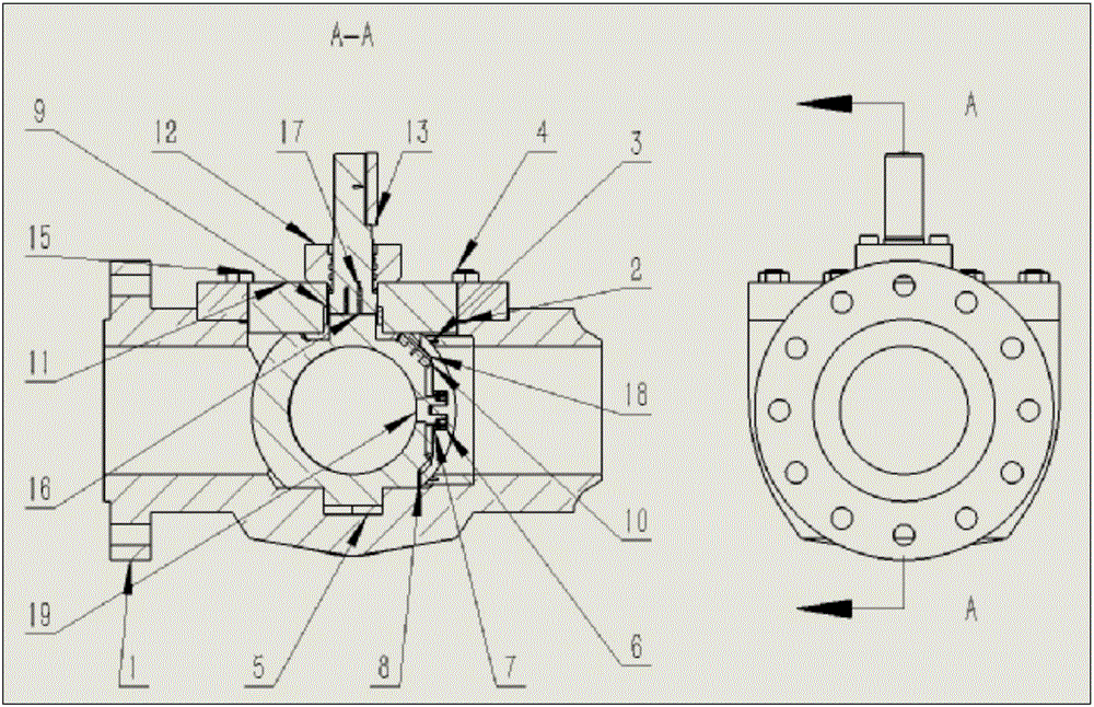
[0049] The forced sealing valve of the present invention can be implemented in various valve body structures such as side-mounted, top-mounted or fully welded. Here, the top-loading type is used as an example to illustrate.

[0050] The top-loading valve body (1) and the upper cover (11) are manufactured by a mature casting process. Later, after machining, the parts meet the assembly size. The rest of the metal parts will be forgings. After machining in the later stage, the parts meet the assembly requirements (so there is no processing difficulty in the parts, and some parts can directly use the same standard parts, such as: bolts, nuts, screws, etc.).

[0051] The following highlights the assembly process:

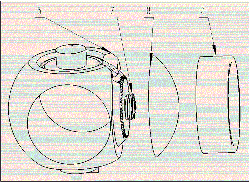
[0052] 1. Assembly of valve seat (3) ( Figure 9 ):

[0053] The valve seat (3) can be directly pressed into the reserved position of the top-mounted valve body with an interference fit, such as Figure 7 shown. The sealing between the valve seat and the valve bod...


PUM


Abstract

The invention relates to a forced seal ball valve. The forced seal ball valve is characterized in that a torque transferring gear set and a screw pressing mechanism are integrated on a valve ball base body (5), 90-degree opening and closing precise limiting is designed for a valve ball lower pivot and a valve body lower pivot cavity, a torsional spring (17) is mounted between a valve ball upper pivot and a valve rod, and the pre-tightening torque of the torsional spring (17) enables a valve ball assembly to shrink and be locked together within 90-degree stroke beyond a valve closing angle; and after the valve ball assembly runs to the closing angle, the valve closing torque of the valve rod is transferred to the screw pressing mechanism through the gear set, and forced seal is realized. When the valve is opened, the valve ball assembly first shrinks and is locked under the action of the torsional spring, and then runs for 90 degrees towards full openness. The valve is compact in structure and truly realizes non-friction opening and closing.

Description

technical field [0001] In the field of fluid control, such as oil and gas production process switching, pipeline shut-off, metering, pressure regulation, molecular sieve switching, compressor inlet and outlet, hydrogen working conditions in oil refining process, air separation of ammonia synthesis equipment, etc., frequent operations and fluid switch control and In the field with strict shut-off tightness, it is required that the valve can produce as little pressure drop as possible in the straight-through state, and can provide a forced torque seal that is not affected by the pressure of the pipeline medium. Positive sealing ball valves are recognized as the ideal solution. Background technique [0002] However, the traditional lifting rod type forced sealing ball valve represented by the American ORBIT valve adopts the design of the lifting valve stem track guide. There is still relative sliding friction in the final engagement stage of the sealing surface, and the fricti...

Claims


Application Information

Patent Timeline
IPC IPC(8): F16K5/06F16K5/20
CPCF16K5/06F16K5/204F16K5/0605
Inventor 刘晓琦
Owner 刘晓琦
Why Eureka
Try Eureka