Light-operated LED energy saving control system based on buffer-type trigger circuit
An energy-saving control system and trigger circuit technology, applied in the electronic field, can solve the problems of inaccurate brightness signal processing and unstable output current, and achieve the effects of ensuring stability, prolonging service life, and stable brightness.
- Summary
- Abstract
- Description
- Claims
- Application Information
AI Technical Summary
Problems solved by technology
Method used
Image
Examples
Embodiment
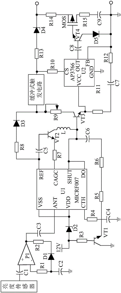
[0019] Such as figure 1 As shown, the present invention is mainly composed of a control chip U1, a brightness sensor, a transistor VT1, a resistor R3, a resistor R4, a polar capacitor C4, a Zener diode D2, a buffer trigger circuit, a signal receiving circuit, a current adjustment circuit, and a linear drive circuit. composition.
[0020] During implementation, the N pole of the Zener diode D2 is connected to the VDD pin of the control chip U1, and its P pole is connected to the base of the triode VT1 after passing through the resistor R3. The positive pole of the polarity capacitor C4 is connected to the CTH pin of the control chip U1 through the resistor R4, and the negative pole thereof is grounded. The signal receiving circuit is connected in series between the brightness sensor and the ANT pin of the control chip U1. The current adjustment circuit is respectively connected with the emitter of the triode VT1 and the control chip U1. The linear drive circuit is connected ...
PUM
 Abstract
Description
Claims
Application Information
 - Generate Ideas
- Intellectual Property
- Life Sciences
- Materials
- Tech Scout
- Unparalleled Data Quality
- Higher Quality Content
- 60% Fewer Hallucinations
Browse by: Latest US Patents, China's latest patents, Technical Efficacy Thesaurus, Application Domain, Technology Topic, Popular Technical Reports.
© 2025 PatSnap. All rights reserved.Legal|Privacy policy|Modern Slavery Act Transparency Statement|Sitemap|About US| Contact US: help@patsnap.com


