
Ignition control apparatus and its control process

An ignition control and ignition device technology, which is applied in the field of pyrotechnics manufacturing, can solve the problems of uncontrollable detonation process of ordinary electric detonators, affecting the safety of detonators, and poor delay accuracy, so as to improve safety and reliability and reduce the risk of heavy metals. Use, delay time for precise effects

Active Publication Date: 2009-06-24
南通炜天电子科技有限公司
View PDF0 Cites 9 Cited by
  • Summary
  • Abstract
  • Description
  • Claims
  • Application Information

AI Technical Summary

Problems solved by technology

The main drawback of this detonation control process is:
This design not only has poor delay accuracy, but also the delay time cannot be changed
In addition, since the delay body contains heavy metals such as delay medicine and lead, this electric detonator will cause the dissipation of heavy metals after use, and the combustion of the delay medicine will also cause environmental pollution.
[0004] 2. The detonation process of ordinary electric detonators is uncontrollable. It enters the detonation process when it is powered on. It is irreversible and cannot be interrupted in case of emergency. There are potential safety problems.
[0005] 3. Since the ignition head is directly connected to the detonator pin, external interference such as electrostatic discharge, radio frequency radiation, and stray current will directly affect the safety of the detonator during production, storage and use.

Method used


Image

  • Ignition control apparatus and its control process
  • Ignition control apparatus and its control process
  • Ignition control apparatus and its control process

Examples


Embodiment Construction

[0040] The technical solution of the present invention will be described in further detail below in conjunction with the accompanying drawings and specific embodiments.

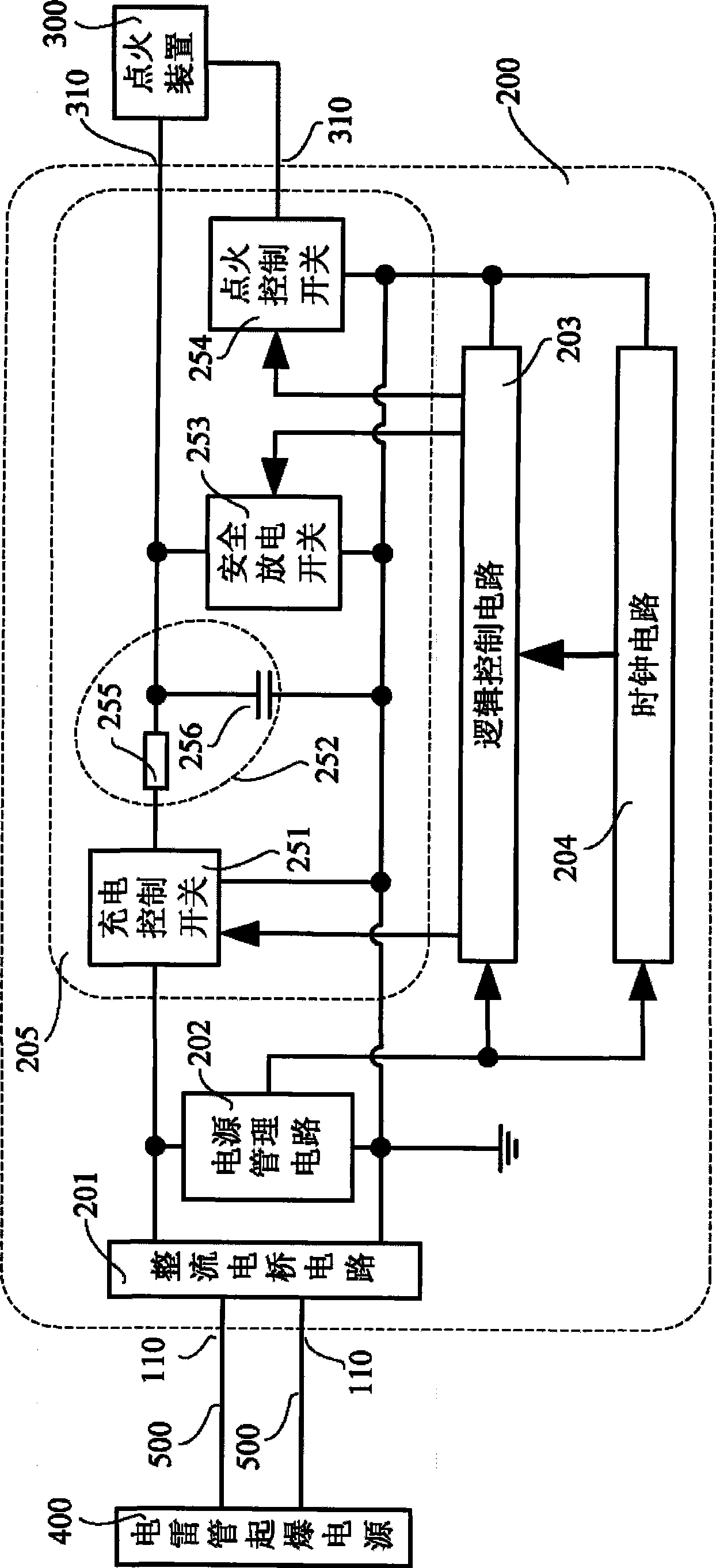
[0041]The ignition control device 200 includes a rectifier bridge circuit 201, a power management circuit 202, a logic control circuit 203, a clock circuit 204, and an ignition control circuit 205, such as figure 1 . The detailed description is as follows:

[0042] 1. One end of the rectifier bridge circuit 201 is connected to the power management circuit 202 and the ignition control circuit 205 at the same time, and one end is grounded; the other two ends lead to the outside of the ignition control device 200, and are connected to the electric detonator detonation power supply 400 outside the ignition control device 200, forming The power input terminal 110 of the ignition control device 200 . The rectifier bridge circuit 201 is used to convert the polarity of the energy input through the power input term...


PUM


Abstract

The invention provides an ignition control device, which comprises a bridge rectifier circuit, a power management circuit, a logic control circuit, a clock circuit and an ignition control circuit, wherein, the ignition control circuit comprises a charge control switch, an RC low pass filter, a safety discharge switch and an ignition control switch; and the RC low pass filter comprises a current-limiting resistor and a storage capacitor. The invention further provides the control flow of the ignition control device, which comprises an initialization control flow, an ignition control flow and other steps, wherein, the ignition control flow is carried out according to the following steps: the logic control circuit transmits a control signal, disconnects the safety discharge switch and closes the charge control switch; the logic control circuit starts electronic delay after reaching the desired charging time; and the logic control circuit transmits the control signal and closes the ignition control switch after reaching the desired delay time. Therefore, the energy for initiation can be controlled safely and reliably, thereby improving the ignition safety.

Description

technical field [0001] The invention relates to the technical field of pyrotechnics manufacture, in particular to an ignition control device applicable to an electric detonator and a control process thereof. Background technique [0002] In the traditional electric detonator ignition control, the electric detonator is connected in parallel or in series to the detonation energy supply line drawn from the detonation controller of the electric detonator. The main drawback of this detonation control process is: [0003] 1. Ordinary electric detonators use a delay body to achieve the delayed detonation function. This design not only has poor delay accuracy, but also the delay time cannot be changed. In addition, since the delay body contains heavy metals such as delay medicine and lead, this electric detonator will cause the dissipation of heavy metals after use, and the combustion of the delay medicine will also cause environmental pollution. [0004] 2. The detonation proces...

Claims


Application Information

Patent Timeline
IPC IPC(8): F42D1/055
Inventor 颜景龙刘星李风国赖华平张宪玉
Owner 南通炜天电子科技有限公司
Learn More