Light-emitting diode epitaxial wafer and preparation method thereof
A technology of light-emitting diodes and epitaxial wafers, applied in the direction of electrical components, circuits, semiconductor devices, etc., can solve the problems of poor substrate adhesion and high cost, and achieve the effect of improving the peeling yield
- Summary
- Abstract
- Description
- Claims
- Application Information
AI Technical Summary
Problems solved by technology
Method used
Image
Examples
Embodiment 1
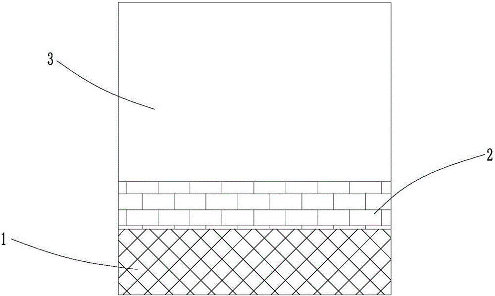
[0034] Such as figure 1 As shown, the traditional gallium nitride-based epitaxial wafer includes a buffer layer 2 and an epitaxial structure layer 3 from the substrate 1 to the surface layer. If the epitaxial structure layer 3 is to be stripped, a laser device must be used, and the stripping yield is not good.
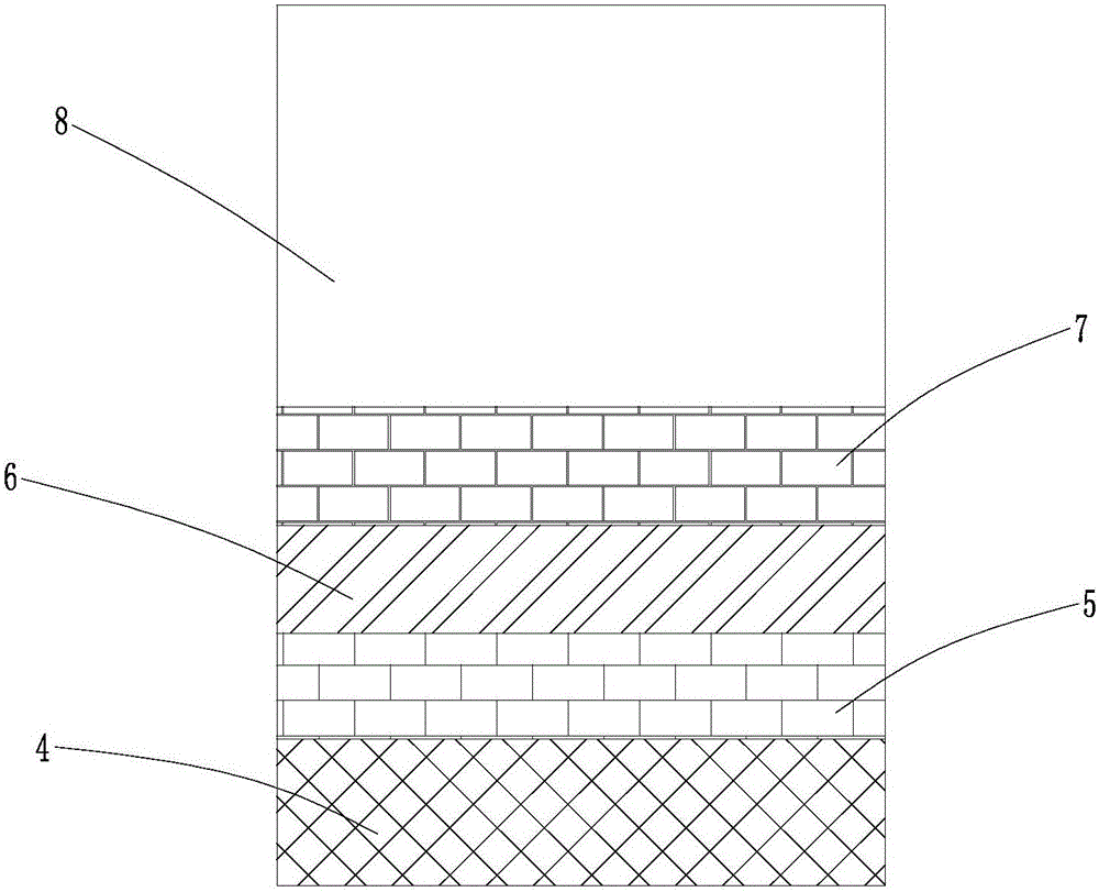
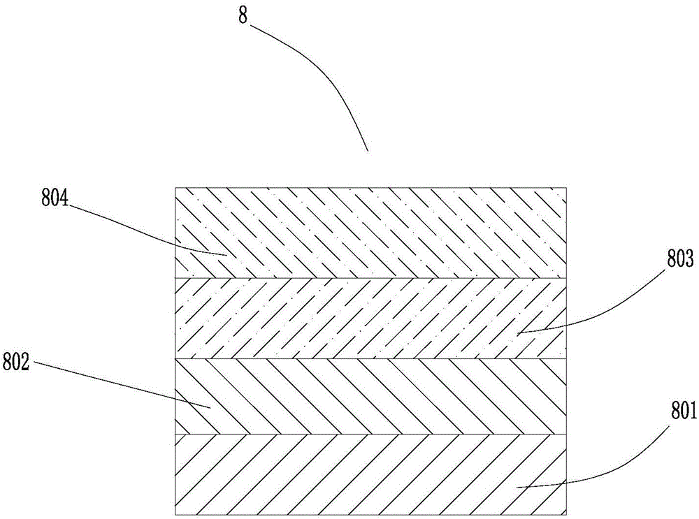
[0035] Such as figure 2 , image 3 As shown, the light-emitting diode epitaxial wafer of the present application, the epitaxial wafer includes a first buffer layer 5, a graphene layer 6, a second buffer layer 7 and an epitaxial structure layer 8 from the substrate 4 to the surface layer; the epitaxial structure layer 8 is formed from the second buffer layer 7 The surface layer is composed of an N-type semiconductor layer 801 , a multiple quantum well layer 802 , a P-type electron blocking layer 803 and a P-type semiconductor layer 804 .
[0036] The substrate 4 is a sapphire substrate.
[0037] The first buffer layer is SiCN with a thickness of 30-40nm; the composi...
Embodiment 2
[0046] The difference between embodiment 2 and embodiment 1 is: the difference of preparation method
[0047] 1) At a temperature of 1200°C, feed carbon source (CBr4), silicon source (SiH4) and nitrogen source (NH3) into the reaction chamber, and grow 30nm SiCN on the sapphire substrate as the first buffer layer; the first buffer layer The silicon content on the side close to the sapphire substrate is controlled below 10%, while the silicon content on the other side is greater than 30%;
[0048]2) At a temperature of 1200°C, feed carbon source (CBr4) and silicon source (SiH4) to grow 8nm silicon carbide on the first buffer layer; after that
[0049] At a temperature of 1500°C and a pressure of <1 Torr, silicon atoms are volatilized to form a graphene layer;
[0050] 3) At a temperature of 1000°C, feed carbon source (CBr4), silicon source (SiH4) and nitrogen source (NH3) into the reaction chamber, and grow a layer of SiCN on the graphene layer as the second buffer layer; or at...
Embodiment 3
[0053] The difference between embodiment 3 and embodiment 1 is; the difference of preparation method
[0054] 1) At a temperature of 850°C, feed carbon source (CBr4), silicon source (SiH4) and nitrogen source (NH3) into the reaction chamber, and grow 35nm SiCN on the sapphire substrate as the first buffer layer; the first buffer layer The silicon content on the side close to the sapphire substrate is controlled below 10%, while the silicon content on the other side is greater than 30%;
[0055] 2) At a temperature of 850°C, feed carbon source (CBr4) and silicon source (SiH4) to grow 12nm silicon carbide on the first buffer layer; then
[0056] At a temperature of 1400°C and a pressure of <1 Torr, silicon atoms are volatilized to form a graphene layer;
[0057] 3) At a temperature of 750°C, feed carbon source (CBr4), silicon source (SiH4) and nitrogen source (NH3) into the reaction chamber, and grow a layer of SiCN on the graphene layer as the second buffer layer; or at temper...
PUM
 Abstract
Description
Claims
Application Information
 - Generate Ideas
- Intellectual Property
- Life Sciences
- Materials
- Tech Scout
- Unparalleled Data Quality
- Higher Quality Content
- 60% Fewer Hallucinations
Browse by: Latest US Patents, China's latest patents, Technical Efficacy Thesaurus, Application Domain, Technology Topic, Popular Technical Reports.
© 2025 PatSnap. All rights reserved.Legal|Privacy policy|Modern Slavery Act Transparency Statement|Sitemap|About US| Contact US: help@patsnap.com


