Ceramic sealing type rotational steam valve

A ceramic sealing and rotary technology, used in the field of steam valves, can solve the problems of cavitation erosion of seals, valve inner leakage and outer leakage valve service life, corrosion and other problems, and achieve good sealing performance, fast switching speed and long service life. Effect

Inactive Publication Date: 2016-08-31
YINGQIAO MACHINERY MFG
View PDF6 Cites 0 Cited by
  • Summary
  • Abstract
  • Description
  • Claims
  • Application Information

AI Technical Summary

Problems solved by technology

[0003] The structure of the existing stop valve and gate valve is that the inlet of the valve is connected to the upper part of the valve cavity, so that the valve stem in the valve cavity is easily corroded by the medium. The phenomenon of external leakage; the switching action of the globe valve and the gate valve is to drive the sealing disc to open and close by operating the valve stem to move up and down, so the closing force when the valve is closed causes the valve disc and the valve seat to be squeezed and worn, which affects the use. service life; especially in the high temperature steam and high temperature condensed water conditions in the steam system, the seals of metal materials are prone to cavitation erosion and corrosion
Therefore, the frequent internal and external leakage of the valves used in the steam system and the service life of the valves are common problems for all users.

Method used


Image

  • Ceramic sealing type rotational steam valve
  • Ceramic sealing type rotational steam valve

Examples


Embodiment Construction

[0016] The following embodiments will further illustrate the present invention in conjunction with the accompanying drawings.

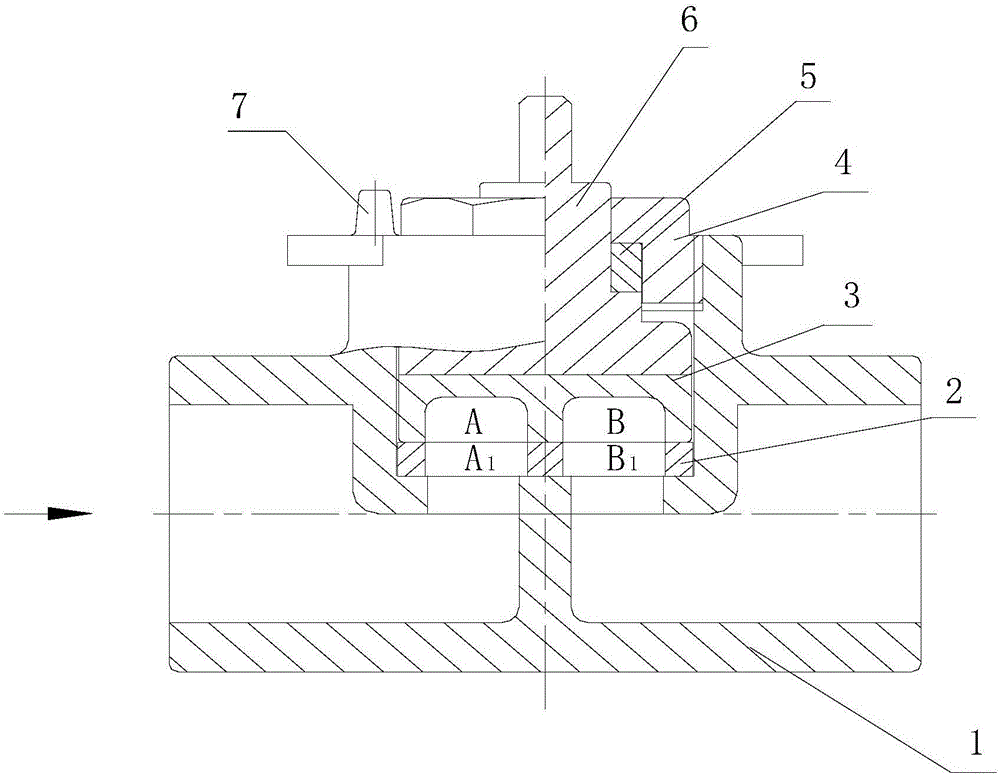
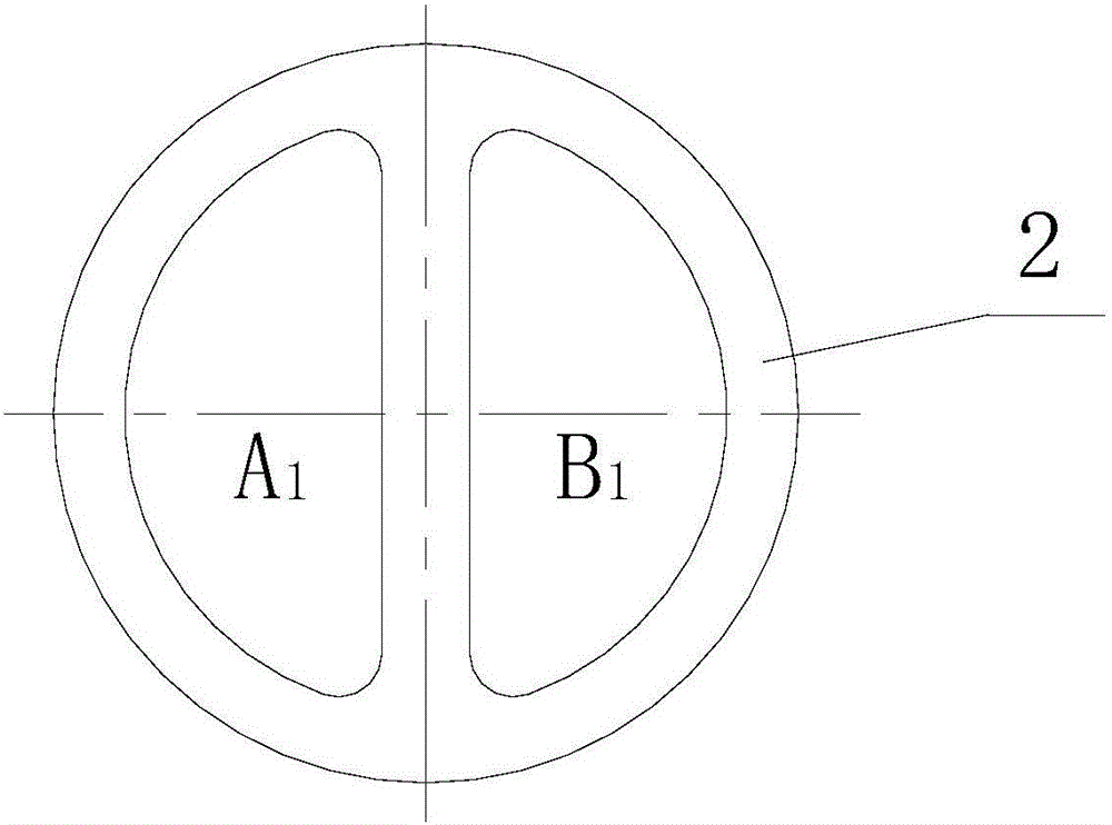
[0017] see figure 1 and 2 , the embodiment of the present invention is provided with a valve body 1, a lower seal ring 2, an upper seal cover 3, a compression nut 4, an adjustment washer 5, an operating rod 6, and a limit post 7; the lower seal ring 2 is loaded into the valve body 1 At the bottom of the inner cavity, the lower sealing ring 2 is connected with the valve body 1 as a whole; the upper sealing cover 3 is arranged on the upper part of the lower sealing ring 2; the lower end of the operating rod 6 is provided with a cross boss, and the top of the upper sealing cover 3 is provided with a cross groove. The cross convex platform is inserted into the cross concave platform, and the operating rod 6 drives the upper sealing cover 3 to rotate; the inner hole of the compression nut 4 is provided with a concave platform, and the outer circle of the ...


PUM


Abstract

The invention provides a ceramic sealing type rotational steam valve, relates to a steam valve. The ceramic sealing type rotational steam valve is of a non-external-leakage structure which is manufactured from a ceramic sealing material and in a rotating sealing manner; the ceramic sealing type rotational steam valve is applicable to a steam system and a high-temperature condensation water condition. The ceramic sealing type rotational steam valve is provided with a valve body, a lower sealing ring, an upper sealing cover, a compressing nut, an adjusting gasket, an operating rod and limiting columns, wherein the lower sealing ring is mounted to the bottom part of an inner chamber of the valve body and is integrally connected with the valve body; the upper sealing cover is arranged at the upper part of the lower sealing ring; a cross boss is arranged at the lower end of the operating rod; a cross groove is formed in the top part of the upper sealing cover; the cross boss is sleeved with a cross concave platform; the operating rod can drive the upper sealing cover to rotate; an inner hole of the compressing nut is provided with a concave platform; outer threads are formed in an outer circle of the compressing nut; the adjusting gasket is mounted into the concave platform at the inner hole of the compressing nut; the operating rod is sleeved with the inner hole of the compressing nut and inner hole of the adjusting gasket; the outer threads in the outer circles of the compressing nut are screwed into an inner chamber of the valve body and are screwed and compressed with the inner threads in the upper part; the two limiting columns are arranged on the upper end surface of the valve body and used for limiting a switch valve.

Description

technical field [0001] The invention relates to a steam valve, in particular to a ceramic-sealed rotary steam valve suitable for the working conditions of a steam delivery pipe network and a high-temperature condensed water recovery system. Background technique [0002] In the steam system, the commonly used valves are metal-sealed globe valves or gate valves. Globe valves have straight-through and right-angle types, and the connection methods include internal thread, external thread, flange connection and welding connection, etc.; gate valves have straight-through type, and the connection methods include internal thread connection, flange connection or welding connection, etc. The opening and closing methods of globe valve and gate valve are all operated by manual, electric, pneumatic, hydraulic or gear transmission. Close the valve. [0003] The structure of the existing stop valve and gate valve is that the inlet of the valve is connected to the upper part of the valve ...

Claims


Application Information

Patent Timeline
Patent Type & Authority Applications(China)
IPC IPC(8): F16K3/04F16K3/314F16K27/04
CPCF16K3/04F16K3/314F16K27/045
Inventor 洪新伟洪新强洪有福洪文财陈晓东吴万发陈亚山李海东洪育洁
Owner YINGQIAO MACHINERY MFG
Why Eureka
Try Eureka