Two-way sealing knife gate valve with self-sealing and elastic compensating seat

An elastic compensation and two-way sealing technology, which is applied in the field of knife gate valves, can solve the problems of valve stuffing box leakage, poor sealing effect, and small sealing specific pressure, so as to improve sealing performance, avoid medium leakage, and achieve good sealing performance.

Active Publication Date: 2017-06-06
WUXI SMART AUTO CONTROL ENG CO LTD
View PDF5 Cites 0 Cited by
  • Summary
  • Abstract
  • Description
  • Claims
  • Application Information

AI Technical Summary

Problems solved by technology

The rigid seal of the knife plate is forced to press the knife plate to the valve seat through the wedge-shaped corner at the bottom of the knife plate. This structure has good one-way sealing performance, but the two-way sealing effect is poor
The knife plate is self-sealing and presses the knife plate to the valve seat through the medium pressure. The valve seat of this structure is made of rubber material and has good sealing performance, but in the working conditions such as particles and slurry, the rubber product is not wear-resistant and has a short service life; If the valve seat made of PTFE is used, the sealing effect is poor due to the small sealing specific pressure under low pressure conditions.
The above two sealing structures will cause radial displacement of the knife plate during the sealing process, which will easily lead to leakage of the stuffing box of the valve

Method used


Image

  • Two-way sealing knife gate valve with self-sealing and elastic compensating seat
  • Two-way sealing knife gate valve with self-sealing and elastic compensating seat
  • Two-way sealing knife gate valve with self-sealing and elastic compensating seat

Examples


Embodiment Construction

[0018] Below the present invention will be further described in conjunction with the embodiment in the accompanying drawing:

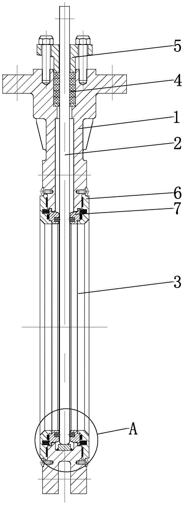
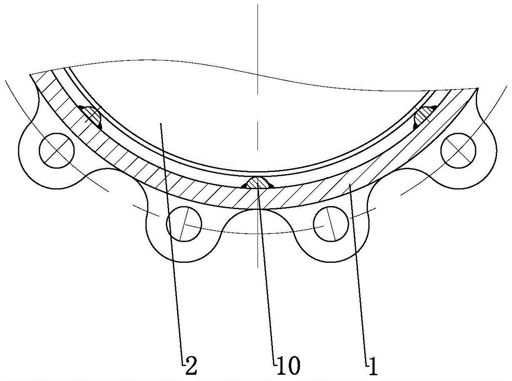
[0019] Such as Figure 1~3 As shown, the present invention mainly includes a valve body 1 , the lower part of the valve body 1 is provided with a left and right through chamber 3 , and the medium can flow along the passage chamber 3 of the valve body 1 . A knife plate 2 is provided in the inner cavity of the valve body 1 , and the knife plate 2 can slide up and down along the inner cavity of the valve body 1 to control the opening and closing of the passage cavity 3 .

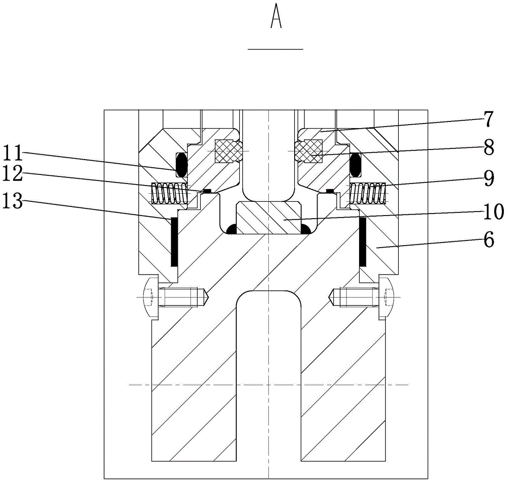
[0020] The pressure ring 6 is arranged on both sides of the passage chamber 3 of the valve body 1 , and the inner side of the pressure ring 6 is provided with a base 7 , and a spring 9 is arranged between the base 7 and the pressure ring 6 , and the spring 9 presses the base 7 tightly. A T-shaped valve seat groove is provided on the side of the base 7 facing the knife plate 2, and a T-...


PUM


Abstract

The invention relates to a knife gate valve, in particular to a two-way sealed knife gate valve with self-sealing and elastic compensation valve seats, and belongs to the technical field of the knife gate valve. The knife gate valve comprises a valve body, the two sides of a through cavity of the valve body are provided with pressing rings, bases are arranged in the pressing rings and springs used for pressing the bases are arranged between the bases and the pressing rings; the sides, facing a knife board, of the bases are provided with T-shaped valve seat slots in which T-shaped valve seats are connected, and the inner sides of the valve seats can be closely in contact with the knife board by pressing the springs. According to the knife gate valve provided by the invention, the valve seat can be enabled to press to the knife board all the time due to the poor stressed area of the valve seat; furthermore, the valve can be sealed well at the low pressure working station by additionally installing the compression springs; in addition, the compression springs can be effectively isolated by the spring isolation structure, therefore the compression springs can be prevented from being locked because compression spring mounting holes are blocked by a sizing agent, non-pure mediums containing particulates and the like.

Description

technical field [0001] The invention relates to a knife gate valve, specifically a bidirectional sealing knife gate valve with a self-sealing and elastic compensating valve seat, belonging to the technical field of knife gate valves. Background technique [0002] Knife gate valve, also known as knife-type slab gate valve, is more and more used for the adjustment and cut-off of various low-pressure conditions due to its simple structure, small installation space, and light weight; at the same time, due to its thin valve body and small flow resistance , especially suitable for all kinds of powder, slurry, medium containing particles and suspended matter. [0003] In many chemical companies, the knife gate valve is not only used as the finished product discharge valve, but also used as the feed valve of the reactor. The medium is driven by the pump to flow through the knife gate valve to the reactor. When the valve is closed, the medium is cut off. When the reactor reacts, the...

Claims


Application Information

Patent Timeline
Patent Type & Authority Patents(China)
IPC IPC(8): F16K3/18F16K3/30F16K41/02
CPCF16K3/18F16K3/30F16K41/02
Inventor 陈彦张程张志超王文明
Owner WUXI SMART AUTO CONTROL ENG CO LTD
Why Eureka
Try Eureka