Power electronic transformer topology structure for self-balancing of multi-level DC bus

A technology of DC bus and power electronics, applied in the direction of converting AC power input to AC power output, converting AC power input to DC power output, electrical components, etc., it can solve the unbalanced DC side capacitor voltage, complex control algorithm, and difficult to implement and other problems to achieve the effect of simplifying the control algorithm

Active Publication Date: 2016-08-24
TSINGHUA UNIV
View PDF2 Cites 13 Cited by
  • Summary
  • Abstract
  • Description
  • Claims
  • Application Information

AI Technical Summary

Problems solved by technology

[0004] The diode-clamped topology is the most commonly used multi-level topology, but the DC side capacitor voltage imbalance is the main problem in its control
In the case of transmitting active power, the circuit needs to perform capacitance balance control, which makes the control algorithm of the circuit more complicated as the number of levels increases
At present, there are many researches on the algorithm of capacitor balance on the DC side of the diode clamp topology, but most of them can only achieve capacitor voltage equalization control for the three-level topology, and the five-level topology can only be realized under specific conditions. When the number of levels is further increased , the control of DC side capacitor voltage balance will be difficult to achieve

Method used


Image

  • Power electronic transformer topology structure for self-balancing of multi-level DC bus
  • Power electronic transformer topology structure for self-balancing of multi-level DC bus
  • Power electronic transformer topology structure for self-balancing of multi-level DC bus

Examples


Embodiment Construction

[0024] The present invention will be described in detail below in conjunction with the accompanying drawings and embodiments.

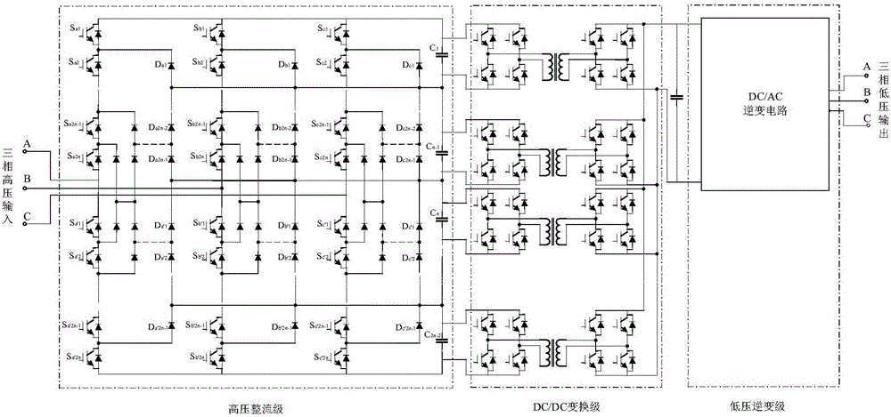
[0025] Such as figure 1 As shown, the present invention provides a multi-level DC bus self-balancing power electronic transformer topology, which includes a high-voltage rectifier circuit, a DC / DC conversion circuit and a low-voltage DC / AC inverter circuit. The input end of the high-voltage rectification circuit is connected to the high-voltage three-phase AC power grid, the output end of the high-voltage rectification circuit is connected to one end of the DC / DC conversion circuit through the high-voltage DC bus, and the other end of the DC / DC conversion circuit is connected to the input end of the low-voltage DC / AC inverter circuit. Connection, the output end of the low-voltage DC / AC inverter circuit is connected to the low-voltage three-phase AC power grid.

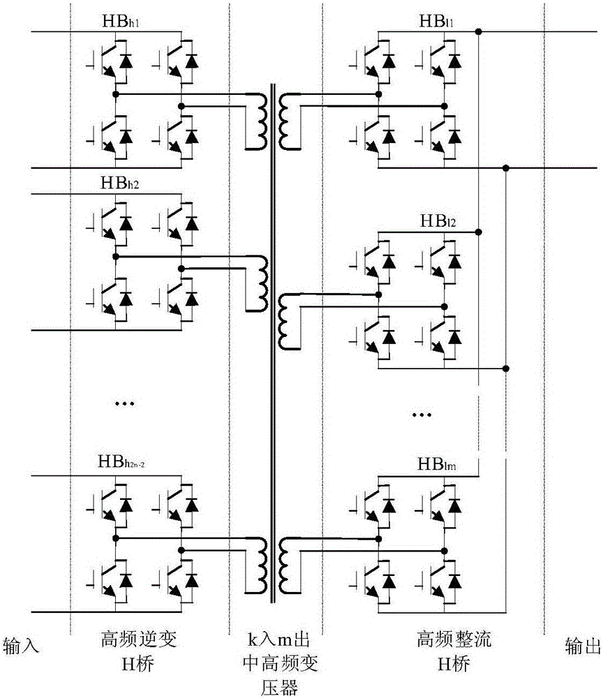
[0026] In the above embodiment, if figure 2 As shown, the high-voltage rectifier circui...


PUM


Abstract

The invention relates to a power electronic transformer topology structure for self-balancing of a multi-level DC bus. The power electronic transformer topology structure is characterized by comprising a high-voltage rectifier circuit, a DC / DC conversion circuit and a low-voltage DC / AC inverter circuit, wherein an input end of the high-voltage rectifier circuit is connected with a high-voltage three-phase AC power network; an output end of the high-voltage rectifier circuit is connected with one end of the DC / DC conversion circuit through a high-voltage DC bus; the other end of the DC / DC conversion circuit is connected with the input end of the low-voltage DC / AC inverter circuit; and the output end of the low-voltage DC / AC inverter circuit is connected with a low-voltage three-phase AC power network. By the topology structure, capacitance-voltage balancing is carried out without voltage feedback of a DC bus capacitor; and the control algorithm of a rectifier side is greatly simplified.

Description

technical field [0001] The invention relates to a topological structure of a power electronic transformer, in particular to a topological structure of a self-balancing power electronic transformer of a multi-level DC bus in the technical field of power electronics. Background technique [0002] Power electronic transformer (Power Electronic Transformer, PET), as a new type of power transmission equipment, has the following advantages compared with traditional power transformers: 1. The volume and weight are greatly reduced. 2. It can realize the AC-DC conversion of any amplitude and frequency, the voltage and current waveforms of the primary and secondary sides are controllable, and the power factor is adjustable. 3. With reactive power compensation and protection functions, no additional supporting devices are required. [0003] Currently, the fully-controlled devices used for PET mostly use Si-based insulated gate bipolar transistors (Insulated Gate Bipolar Transistor, IG...

Claims


Application Information

Patent Timeline
Patent Type & Authority Applications(China)
IPC IPC(8): H02M5/458H02M7/219H02M7/487
CPCH02M5/4585H02M7/219H02M7/487H02M1/007
Inventor 郑泽东李永东王优
Owner TSINGHUA UNIV
Why Eureka
Try Eureka