
Client electricity information collection simulation system for electricity marketing

A technology of electricity consumption information and electricity marketing, applied in the direction of electrical signal transmission system, signal transmission system, application, etc., can solve the problem of unfavorable employee health monitoring, the inability to use confidentiality measures for other purposes, and the inability of employees to provide more comprehensive medical and health care. Welfare and other issues to achieve the effect of simplifying the identity confirmation process, avoiding overcooling or overheating, and increasing the impact speed

Pending Publication Date: 2016-08-24
JUANCHENG POWER SUPPLY CO STATE GRID SHANDONG ELECTRIC POWER CO
View PDF9 Cites 0 Cited by
  • Summary
  • Abstract
  • Description
  • Claims
  • Application Information

AI Technical Summary

Problems solved by technology

[0003] In addition, as a simulation system for electricity collection used by schools or training institutions, users are usually authorized to operate the simulation system only after they have been authorized by the system or pre-registered and logged in to the system. Currently, commonly used identification security systems include passwords and random QR codes. , audio and other technical measures, but the above-mentioned technologies can only realize the authorized use of students, and these confidentiality measures can no longer be used for other purposes
At present, there are many employees and students in electric power training institutions or schools, and it is often necessary to conduct regular physical examinations or collect health information for employees. However, such regular physical examinations cannot collect employees' health information data at any time, that is, they cannot monitor employees' health at any time or periodically. First, this situation is not conducive to the health monitoring of employees in the strong radiation environment of the power system. Second, as a state-owned enterprise, it cannot provide more comprehensive medical and health benefits for employees, and will gradually lose corporate social responsibility and recruitment attractiveness.

Method used


Image

  • Client electricity information collection simulation system for electricity marketing
  • Client electricity information collection simulation system for electricity marketing
  • Client electricity information collection simulation system for electricity marketing

Examples


Embodiment 1

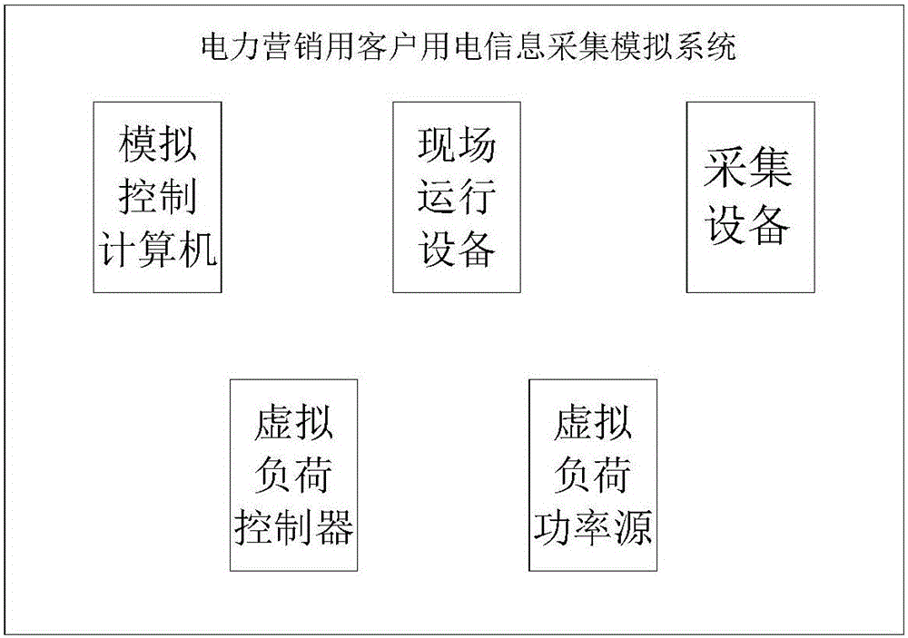
[0048] figure 1 It is a structural schematic diagram of Embodiment 1 of the present invention;

[0049] A simulation system for collecting electricity consumption information of customers for electric power marketing, including: simulation control computer, on-site operation equipment, collection equipment, and multiple virtual load controllers and multiple virtual load power sources.

Embodiment 2

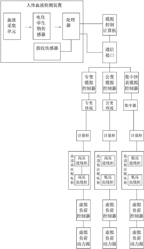
[0051] figure 2 It is a structural schematic diagram of Embodiment 2 of the present invention.

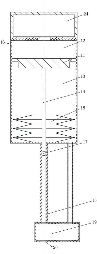
[0052] image 3 It is a schematic structural diagram of the blood collection unit in Embodiment 2 of the present invention; Figure 4 It is a schematic diagram of the blood collection unit in embodiment 2 when emitting emission particles; Figure 5 It is a schematic diagram of the blood collection unit in embodiment 2 when the launching piston is reset;

[0053] In the figure, there are two kinds of arrows, in which the larger arrow in the triangular part indicates the movement direction of the component, and the smaller arrow in the triangular part indicates the flow direction of gas or liquid. The meanings indicated by each reference sign are as follows; 11, launch piston; 12, first cavity; 13, second cavity; 14, launch rod; 15, launch tube; 16, exhaust hole armor; 17, launch particles; 18, Return spring; 19, blood storage cavity; 20, emission through hole; 24, gas generatin...

Embodiment 3

[0076] Figure 6 is a schematic structural diagram of the blood collection unit in Example 3 of the present invention; in the figure, image 3 The meanings indicated by the reference signs that have already appeared continue to apply image 3 The meanings in , the meanings of the newly appearing reference signs are as follows; 21. Buffer hole;

[0077] The difference between this embodiment and embodiment 2 is:

[0078]The second chamber 13 is also provided with a buffer hole 21 for reducing the recoil when the projectile particles 17 are launched. Set diagonally outward.

[0079] By setting the buffer hole 21 on the second cavity 13, the gas flow direction changes during the process of exhausting from the buffer hole 21 after encountering the buffer hole 21, and naturally receives an upward force in the figure. According to the law of action force and reaction force, at the same time, the launching chamber is subjected to a downward force in the figure, which can have a c...


PUM


Abstract

The invention relates to a client electricity information collection simulation system for electricity marketing. The system comprises a simulation control computer, field operation equipment, collection equipment, a plurality of virtual load controllers, a plurality of virtual load power sources, a communication interface, a subsystem simulation controller and an intelligent electric meter. A human body blood detection device is further arranged on the simulation control computer and comprises a blood collection unit, an electrochemical biological sensor, an identity recognition module and a processor. The blood collection unit is used for collecting human body blood and conveying the collected blood to the electrochemical biological sensor. The processor is used for receiving and processing the data collected by the electrochemical biological sensor, obtaining human body blood data, matching the human body blood data with identity information and sending the human body blood data to a remote server through a communication interface. The system can detect user blood and transmits information of the user blood to a medical institution through the simulation control computer, and therefore detection convenience of a worker is improved.

Description

technical field [0001] The invention belongs to the technical field of smart home, and in particular relates to a simulation system for collecting and simulating customer electricity consumption information for electricity marketing. Background technique [0002] At present, the construction of electricity collection and simulation systems of various power marketing units basically stays at the level of hardware simulation, and the scale is small. Some training schools did not build electricity collection simulation systems, but purchased some carrier energy meters, energy meters, terminals and collectors, etc., to train students on the principles and functions of the equipment, as well as the configuration and installation of the devices. The power consumption simulation system built by the Shijiazhuang Electric Power Training Center only retrieves the data collected by a branch company on site for a period of time for training, which makes the training data not real-time a...

Claims


Application Information

Patent Timeline
Patent Type & Authority Applications(China)
IPC IPC(8): G08C19/00A61B5/157A61B5/151A61B5/117G01N27/27
CPCA61B5/1172A61B5/150022A61B5/150099A61B5/15134A61B5/157G01N27/27G08C19/00
Inventor 卞艳萍王静史亚丽王佩合黎茹邓亚军刘振杨备战谷艳民陈剑飞张鵾鲁厚轩杨哲周林振
Owner JUANCHENG POWER SUPPLY CO STATE GRID SHANDONG ELECTRIC POWER CO
Learn More