Power distribution cabinet for electric marketing
A technology for power marketing and power distribution cabinets, applied in substation/power distribution device shells, applications, panels/switch station circuit devices, etc., can solve the problems of high labor intensity, easy loss of keys and inconvenient carrying, and achieve reliable assurance Effects of operation, increased impact speed, and improved service life
- Summary
- Abstract
- Description
- Claims
- Application Information
AI Technical Summary
Problems solved by technology
Method used
Image
Examples
Embodiment 1
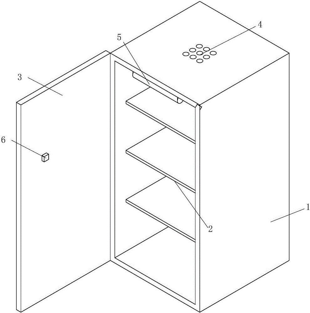
[0045] figure 1 It is a schematic structural diagram of Embodiment 1 of the present invention; in the figure, the meaning of each reference sign is as follows: 1. Cabinet body; 2. Horizontal mounting plate; 3. Cabinet door; 4. Ventilation hole; 5. Lighting lamp; 6. Contact switch
[0046] A power distribution cabinet for electric power marketing includes a cabinet body 1 and a plurality of horizontal mounting plates 2, and a cabinet door 3 is installed on the front of the cabinet body 1.
[0047] A number of ventilation holes 4 and lighting lamps 5 are provided on the top of the cabinet body 1, and a contact switch 6 for controlling the lighting lamps 5 is provided on the cabinet door 3.
Embodiment 2
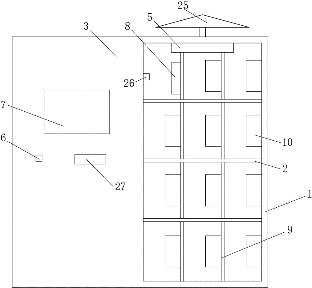
[0049] figure 2 It is a schematic diagram of the structure of Embodiment 2 of the present invention.
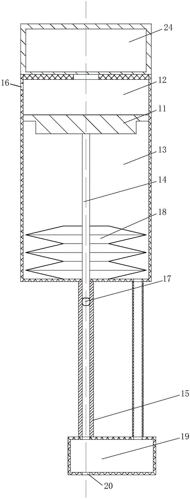
[0050] image 3 It is a schematic diagram of the structure of the blood collection unit in Embodiment 2 of the present invention; Figure 4 It is a schematic diagram of the blood collection unit in Embodiment 2 when emitting particles; Figure 5 It is a schematic diagram of the blood collection unit in Embodiment 2 when the launch piston is reset;
[0051] In the figure, there are two kinds of arrows. The larger arrow in the triangle indicates the direction of movement of the component, and the smaller arrow in the triangle indicates the flow direction of gas or liquid. The meanings of each reference sign are as follows; 7. Touch screen; 8. Controller; 9. Vertical installation board; 10. Power parameter detection equipment; 25. Umbrella; 26. Temperature sensor; 27. Human blood detection device ;
[0052] 11. Launching piston; 12. First cavity; 13. Second cavity; 14. Launching rod;...
Embodiment 3
[0072] Image 6 It is a schematic diagram of the structure of the blood collection unit in Embodiment 3 of the present invention; in the figure, image 3 The meanings of the reference signs that have appeared are used image 3 The meanings of the newly appeared reference signs are as follows; 21. Buffer hole;
[0073] The difference between this embodiment and Embodiment 2 is:
[0074] The second cavity 13 is also provided with a buffer hole 21 for reducing the recoil when the emitting particle 17 is emitted. The buffer hole 21 is provided on the side wall of the second cavity 13 and emits the emitting particle 17 along the emission piston 11. Syncline is set outward.
[0075] By arranging the buffer hole 21 on the second cavity 13, after the gas encounters the buffer hole 21, in the process of exhausting from the buffer hole 21, the flow direction of the gas changes, and naturally receives the upward force in the figure. According to the law of acting force and reaction force, at t...
PUM
 Abstract
Description
Claims
Application Information
 - R&D Engineer
- R&D Manager
- IP Professional
- Industry Leading Data Capabilities
- Powerful AI technology
- Patent DNA Extraction
Browse by: Latest US Patents, China's latest patents, Technical Efficacy Thesaurus, Application Domain, Technology Topic, Popular Technical Reports.
© 2024 PatSnap. All rights reserved.Legal|Privacy policy|Modern Slavery Act Transparency Statement|Sitemap|About US| Contact US: help@patsnap.com


