
Mask plate and array substrate

A technology of array substrate and mask plate, which is applied in the direction of optics, instrumentation, photoplate making process of pattern surface, etc., can solve the problem of excessive etching in the via hole area, achieve the effect of reducing the etching intensity and avoiding the conductivity

Inactive Publication Date: 2016-08-24
BOE TECH GRP CO LTD +1
View PDF2 Cites 4 Cited by
  • Summary
  • Abstract
  • Description
  • Claims
  • Application Information

AI Technical Summary

Problems solved by technology

[0005] The purpose of the present invention is to solve the problem of excessive etching in the via hole area in the existing via hole etching technology

Method used


Image

  • Mask plate and array substrate
  • Mask plate and array substrate
  • Mask plate and array substrate

Examples


Embodiment Construction

[0023] In order to make the technical problems, technical solutions and advantages to be solved by the present invention clearer, the following will describe in detail with reference to the drawings and specific embodiments.

[0024] The present invention provides a solution to the problem of excessive etching at the position of the via hole in the prior art.

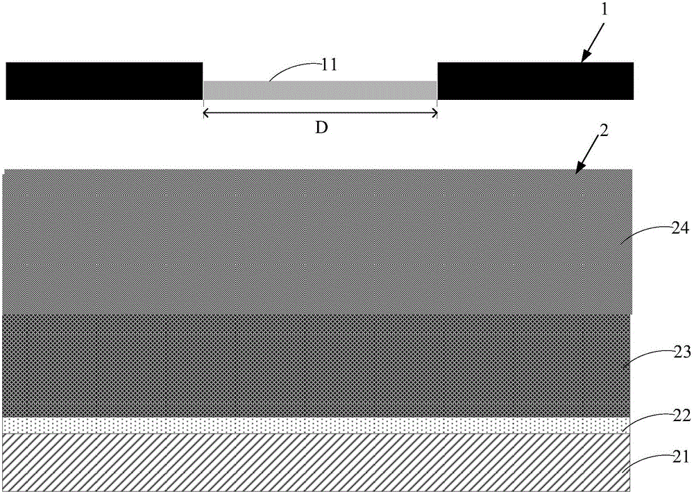
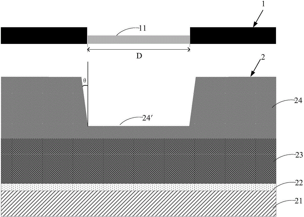
[0025] On the one hand, the embodiment of the present invention provides a mask, which is used to form the pattern of the insulating layer on the array substrate, wherein the insulating layer needs to be formed with via holes, such as figure 1 As shown, the mask plate 1 of this embodiment includes a first region D corresponding to the via hole of the insulating layer, and a semi-transparent pattern 11 is disposed on the first region D.

[0026] further reference Figure 2A , assuming that the mask plate 1 of this embodiment is used to make the via hole of the insulating layer 23 on the array substrate 2, in the specifi...


PUM

PropertyMeasurementUnit
thicknessaaaaaaaaaa
thicknessaaaaaaaaaa

Abstract

The present invention provides a mask plate and an array substrate. The mask plate is used for forming a pattern of an insulating layer on the array substrate, and the insulating layer comprises a via-hole. The mask plate comprises a first region corresponding to the via-hole, wherein the first region is provided with a semipermeable optical pattern. The mask plate disclosed by the present invention is provided with the semipermeable optical pattern in the corresponding via-hole region, based on the design of the semipermeable optical pattern, after exposing a photoresist layer above the via-hole region of the insulating layer, a layer of photoresist pattern with the thin thickness is reserved above the via-hole region of the insulating layer, and the photoresist pattern can reduce the etch rate of the etch gas, so that conductivity reduction of a metal protective layer beneath the via-hole region of the insulating layer after oxidation caused by piercement of the metal layer is avoided.

Description

technical field [0001] The invention relates to the field of display technology, in particular to a mask plate and an array substrate. Background technique [0002] In the manufacturing process of the existing display device, it is necessary to pattern the insulating layer to form via holes, so as to connect wires, jumpers, electrodes, etc. located in different layers. Taking a thin film transistor on a display device as an example, the main function of the via hole in the insulating layer in the thin film transistor is to connect the drain electrode to the pixel electrode of other layers. At present, the most economical and mature drain material is aluminum, but the surface of aluminum is easily oxidized to Al 2 o 3 The insulating layer obviously affects the ohmic contact characteristics of the drain, and seriously deteriorates the device performance of the thin film transistor. [0003] In order to solve this problem, one or more metal barrier layers are usually plated ...

Claims


Application Information

Patent Timeline
Patent Type & Authority Applications(China)
IPC IPC(8): G03F1/54H01L21/77
CPCG03F1/54H01L27/1288
Inventor 徐德智
Owner BOE TECH GRP CO LTD
Learn More