Coreless Armature Inner and Outer Rotor Brushless DC Permanent Magnet Motor

A permanent magnet motor and hollow cup technology, which is applied in the direction of electric components, electromechanical devices, electrical components, etc., can solve the problems of poor winding effect of armature winding cups, insufficient use of wire space, and inability to wind and shape. Achieve the effects of increasing the air gap magnetic flux density, increasing the air gap magnetic flux density, and improving operating efficiency

Active Publication Date: 2019-07-02
ONCE TOP MOTOR MFG
View PDF4 Cites 0 Cited by
  • Summary
  • Abstract
  • Description
  • Claims
  • Application Information

AI Technical Summary

Problems solved by technology

[0004] In the hollow cup armature inner and outer rotor brushless DC permanent magnet motor provided by the present invention, the winding of the hollow cup stator is bonded to the flange and fixed on the end cover to keep absolutely still, and the inner permanent magnet, outer permanent magnet, magnetic conducting ring and The casings are relatively stationary to each other. During the operation of the motor, the casing and the magnetic ring are stationary relative to the inner permanent magnet and the outer permanent magnet, so there is no iron loss caused by the alternating magnetic field, and the inner permanent magnet and the outer permanent magnet are separated. The magnetomotive force is in the form of series, which greatly increases the magnetic flux density of the air gap in the motor. At the same time, the coreless stator winding adopts the form of stacked winding, which can easily realize the winding of wire cups with different performance requirements, and effectively solve the problem of internal iron in the motor. Large loss, low air gap magnetic density, insufficient utilization of wire space in hollow cup production, poor winding effect of armature winding wire cup, and even failure to wind into shape

Method used


Image

  • Coreless Armature Inner and Outer Rotor Brushless DC Permanent Magnet Motor
  • Coreless Armature Inner and Outer Rotor Brushless DC Permanent Magnet Motor
  • Coreless Armature Inner and Outer Rotor Brushless DC Permanent Magnet Motor

Examples


Embodiment 1

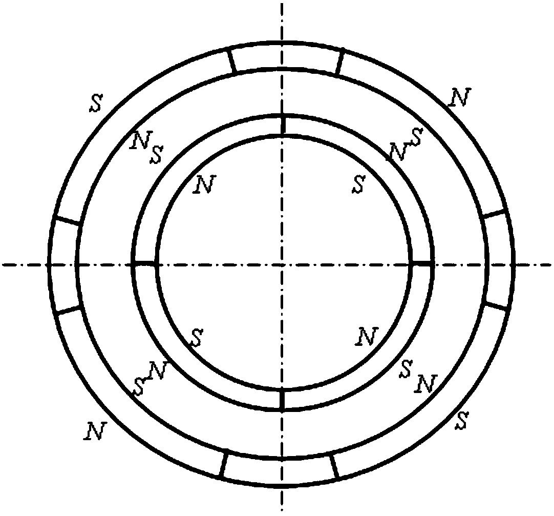
[0033] figure 1 The cross-sectional view of the hollow cup armature inner and outer rotor brushless DC permanent magnet motor provided by the present invention includes a shafting assembly and a moving assembly, and the shafting assembly includes a rotating shaft 10, a bearing 2, a first end cover 3, a hollow cup stator 5 and a The blue plate 4, the moving assembly includes the casing 7, the outer permanent magnet 6, the inner permanent magnet 8, the magnetic conduction ring 9 and the second end cover 12, the hollow cup stator 5 is composed of a cup-shaped skeleton and windings, the left side of the hollow cup stator 5 The end is further fixedly connected with the first end cover 3 by connecting the upper end side of the flange 4, and keeps absolutely still under the working state of the motor. The radial inner side of the hollow cup stator 5 is the inner permanent magnet 8, and the radial outer side of the hollow cup stator 5 is the outer permanent magnet 6; On the inner wal...

Embodiment 2

[0049] The hollow cup armature inner and outer rotor brushless DC permanent magnet motor provided in this embodiment is a permanent magnet motor with a Hall element, and its shaft assembly and moving assembly have the same structure as the permanent magnet motor without a Hall element in Embodiment 1. Similarly, a PCB board 16 , a Hall element 17 and lead wires 18 are added on the basis of the structure of the permanent magnet motor in Embodiment 1.

[0050] Figure 6 It is a cross-sectional view of a hollow cup armature inner and outer rotor brushless DC permanent magnet motor provided in this embodiment, including a shaft assembly and a moving assembly. The shaft assembly includes a shaft 10, a bearing 2, a first end cover 3, The hollow cup stator 5 and the flange 4, the moving assembly includes the casing 7, the outer permanent magnet 6, the inner permanent magnet 8, the magnetic conducting ring 9 and the second end cover 12, and the hollow cup stator 5 is composed of a cup...

Embodiment 3

[0054] The difference between the coreless armature inner rotor brushless DC permanent magnet motor structure provided in this embodiment and the permanent magnet motor structure in Embodiment 1 is that the winding of the coreless stator 5 winding is a series stacked Y-shaped connection.

[0055] Figure 7 It is a schematic diagram of the hollow cup winding series stacked Y-shaped connection method of the hollow cup armature inner and outer rotor brushless DC permanent magnet motor of the present invention. The finished wire package has the wire heads A, B, C and wire tails X, Y, Z of the three-phase winding. B and C are connected in series to increase the number of turns of each phase winding, forming a form of windings stacked in series.

[0056] The hollow cup stator 5 is wound by machine on the skeleton, including winding methods such as winding, oblique winding and assembled winding. It can be freely connected to form a Y-shaped connection or a △-shaped connection. At t...


PUM


Abstract

The invention discloses a moving-coil brushless DC (direct-current) permanent magnet motor with an inner and outer rotor structure. The moving-coil brushless DC permanent magnet motor comprises a shaft assembly and a moving assembly, wherein the shaft assembly comprises a rotating shaft, bearings, a first end cover, a moving-coil stator and a flange plate; the moving assembly comprises a casing, an outer permanent magnet, an inner permanent magnet, a magnetic conducting ring and a second end cover; the moving-coil stator comprises a cup-shaped framework and a winding and is further fixedly connected onto the first end cover through connection with the flange plate, the inner permanent magnet is arranged on the radial inner side of the moving-coil stator, and the outer permanent magnet is arranged on the radial outer side of the moving-coil stator; the inner wall of the inner permanent magnet is arranged on the magnetic conducting ring in a sleeving manner; the outer wall of the outer permanent magnet is tightly attached to the inner wall of the casing; the magnetic conducting ring and the casing are embedded and fixed with the inner side of the second end cover through clamp ports; the first end cover and the second end cover are convex, the first end cover is connected with the rotating shaft through the bearings, the second end cover is fixed with the rotating shaft through screws, and magnetic polarity of the inner permanent magnet is the same as that of the outer permanent magnet in the radial direction.

Description

technical field [0001] The invention relates to the technical field of permanent magnet direct current motors, in particular to a coreless armature brushless direct current permanent magnet motor with inner and outer rotor structures. Background technique [0002] Permanent magnet motors have the characteristics of compact structure, small size, reliable operation, flexible size and shape, especially coreless motors because of their light weight, no cogging effect, small moment of inertia, fast response and stable operation. It is widely used in daily life, industrial production, aerospace and other fields. [0003] At present, the permanent magnet motor still has the following deficiencies: (1) In the permanent magnet motor, the amount of silicon steel sheets and other soft magnetic materials accounts for a relatively large proportion of the total weight of a single motor, and the silicon steel sheets and soft magnetic materials in the alternating magnetic field Due to the...

Claims


Application Information

Patent Timeline
Patent Type & Authority Patents(China)
IPC IPC(8): H02K29/00H02K1/12H02K3/47
CPCH02K1/12H02K3/47H02K29/00
Inventor 张用万
Owner ONCE TOP MOTOR MFG
Why Eureka
Try Eureka