A simple and stable deceleration method for the reaction flywheel of the balloon basket

A technology of reaction flywheel and balloon basket, which is applied in the direction of electric speed/acceleration control, etc., to achieve the effects of improving safety, low investment cost, and avoiding excessive reaction torque

Active Publication Date: 2019-04-23
INST OF OPTICS & ELECTRONICS - CHINESE ACAD OF SCI
View PDF1 Cites 0 Cited by
  • Summary
  • Abstract
  • Description
  • Claims
  • Application Information

AI Technical Summary

Problems solved by technology

[0006] The technical problem to be solved by the present invention is: when the flywheel speed is full due to the reaction of the balloon basket, or when the flywheel speed is not zero and is about to exit the control state, the flywheel should be decelerated smoothly so as not to cause the hanging basket to shake, and to avoid the traditional flywheel deceleration In the method, the closed-loop flywheel system is required, and the control structure is complicated when the anti-twisting mechanism actively provides additional torque

Method used


Image

  • A simple and stable deceleration method for the reaction flywheel of the balloon basket
  • A simple and stable deceleration method for the reaction flywheel of the balloon basket
  • A simple and stable deceleration method for the reaction flywheel of the balloon basket

Examples


Embodiment Construction

[0024] Examples of the present invention are described below. But following embodiment only limits to explain the present invention, and protection scope of the present invention should comprise the whole content of claim, and promptly can realize the whole content of claim of the present invention to those skilled in the art through following embodiment.

[0025] The present invention will be further described by taking the flywheel deceleration embodiment of a certain balloon basket azimuth control system as an example below.

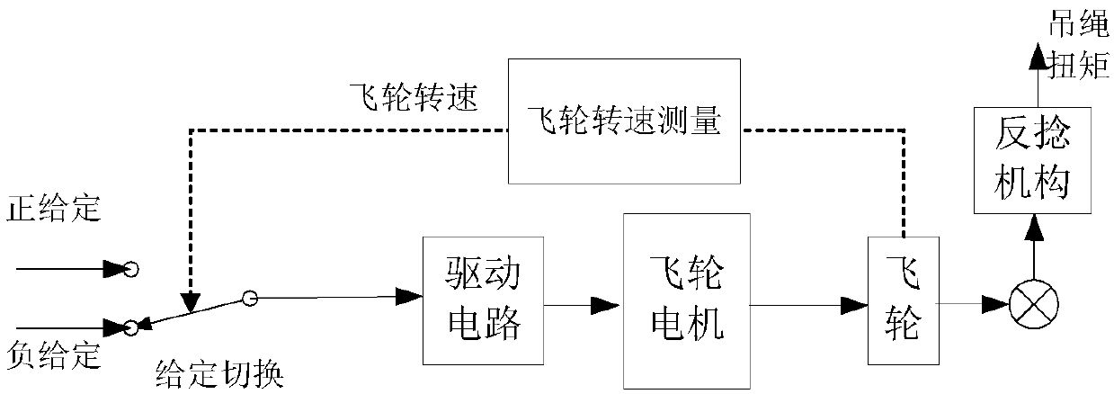
[0026] Such as figure 2 Shown is the structure of the control system when the balloon basket reacts to the flywheel to reduce the speed of the present invention, including the drive circuit, flywheel motor, flywheel, flywheel speed measurement and anti-twisting mechanism. The flywheel speed measurement unit measures the current speed of the flywheel to switch the given value, and the drive circuit converts the given value into a driving voltage and ...


PUM


Abstract

The invention provides a simple and smooth speed reduction method for a reaction flywheel of a balloon nacelle, wherein the simple and smooth speed reduction method is suitable for the balloon nacelles in which a reaction flywheel system and a countertwist mechanism are used for performing direction control. The simple and smooth speed reduction method settles a problem of complicated logical structure of a control system in a previous unloading process for aiming at problems of a requirement for flywheel speed reduction on condition of highest flywheel rotating speed or in a control retreating process of the balloon nacelle. The method particularly comprises the steps of measuring the current speed of the flywheel, comparing the current speed with a target speed, applying a fixed given signal on a flywheel driving circuit according to a comparison result, and furthermore stopping active supplying of a moment by the countertwist mechanism, keeping relative rest between a balloon and a nacelle, thereby realizing smooth speed reduction of the flywheel. According to the system, loop closing by a direction control system of the nacelle is not required in the speed reduction process of the flywheel, and furthermore additional moment supplied by the countertwist mechanism is not required, thereby simplifying structures of a high-altitude balloon nacelle reaction flywheel control system and a countertwist mechanism control system in the unloading process, and reducing design difficulty of a high-altitude balloon nacelle control system.

Description

technical field [0001] The invention belongs to the field of control engineering, and particularly relates to a method for stably reducing the speed of a balloon basket reaction flywheel when the speed is saturated or exits the control state. Background technique [0002] The balloon basket refers to the equipment carrying platform suspended under the floating carriers such as balloons and airships through flexible connections (usually cables). High-energy physics and other scientific fields have broad application prospects. [0003] When the balloon basket is working normally, it needs to control its azimuth and attitude angle (hereinafter referred to as azimuth angle) to ensure that the equipment carried on it can work stably. The azimuth control system of the hanging basket usually consists of two subsystems: the reaction flywheel system and the anti-twist mechanism. The reaction flywheel system measures the azimuth angle, azimuth velocity, and flywheel speed of the han...

Claims


Application Information

Patent Timeline
Patent Type & Authority Patents(China)
IPC IPC(8): G05D13/62
CPCG05D13/62
Inventor 毛耀邓超于伟刘琼曹政
Owner INST OF OPTICS & ELECTRONICS - CHINESE ACAD OF SCI
Why Eureka
Try Eureka