
Synchronous shooting device with function of automatic light source changing

A technology of automatic conversion and photography device, applied in photography, optics, color TV parts, etc., to achieve the effect of easy portability, simple and fast operation

Active Publication Date: 2016-08-10
NEW DIMENSIONAL IMAGINATION DIGITAL TECH BEIJING
View PDF7 Cites 5 Cited by
  • Summary
  • Abstract
  • Description
  • Claims
  • Application Information

AI Technical Summary

Problems solved by technology

[0005] The problem of the prior art that the present invention needs to solve is: the prior art cannot realize the switching of the fully automatic control of the light source in the photographing process and realize continuous automatic shooting at the same time

Method used


Image

  • Synchronous shooting device with function of automatic light source changing
  • Synchronous shooting device with function of automatic light source changing
  • Synchronous shooting device with function of automatic light source changing

Examples


Embodiment 1

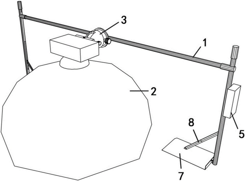
[0026] refer to Figure 1-Figure 4 As shown, the present invention provides a synchronous photography device for automatically changing light sources, including a support 1 , a stand 7 , a moving platform 3 , a shading cover 2 , a light array group 4 , a connection circuit 6 and a control circuit 5 .

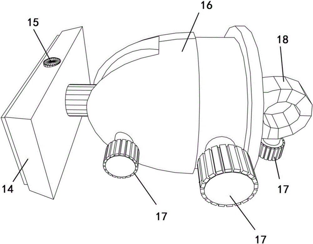
[0027] The mobile platform 3 is installed on the support 1 and slides along the support 1 . The mobile just platform 3 includes a quick-loading plate 14, a leveling device 16 and a fixing ring 18; The knob 17 for tightening it to the bracket 1 is provided on the fixing ring 18 . The leveling device 16 is installed between the fixed ring 18 and the quick release plate 14, the fixed ring 18 slides on the cross bar of the bracket 1, and the photographic equipment is fixed on the quick release plate 14 superior.

[0028] Both sides of the support 1 are provided with foldable stand feet 7 , and joint bearings 9 are used to connect the stand and the support 1 . A support rod 8 is ...


PUM


Abstract

The invention relates to the shooting device field, particularly to a synchronous shooting device with the function of automatic light source changing. The synchronous shooting device comprises a support, a mobile bench, a shielding cover, a light array group, and a control circuit. The mobile bench is installed on the support and can slide on the support. The light array group is installed inside the shielding cover. The mobile bench and the light array group are connected with the control circuit. The skeleton of the shielding cover has a segmented structure; and the support has a telescopic structure. Because of the extendibility of the support and the foldability of the shielding umbrella, the device can be carried conveniently and can be applied to various shooting environments; and the shielding range can be adjusted according to the size of a shot object. With the mobile bench, the shooting angel of a shooting instrument as well the relative position of the object can be adjusted conveniently; and the operation becomes simple and rapid. The control circuit controls automatic light source changing and automatic shooting by the shooting instrument, so that light source switching and continuous shooting during the RTI shooting process can be realized completely.

Description

technical field [0001] The invention relates to the field of photography devices, in particular to a synchronous photography device for automatically changing light sources. Background technique [0002] Reflection Transformation Imaging (RTI) is a computational photography technique that captures the surface shape and color of an item, and provides interactive lighting data through illumination in any direction, and then uses a camera to capture a set of photos of the item at the same location under different light conditions . By simply encoding this group of photos to obtain data, and then using the pixel-by-pixel reflectance function, RTI technology can use light in any direction within the range of the camera to generate a new image. RTI photography technology is applied to virtual inspection and cultural relics research. Due to the characteristics of the material and texture characteristics of the object, the interaction between light and objects is very important for...

Claims


Application Information

Patent Timeline
IPC IPC(8): H04N5/235H04N5/232G03B15/05
CPCG03B15/05H04N23/66H04N23/74
Inventor 王日月王振党杰
Owner NEW DIMENSIONAL IMAGINATION DIGITAL TECH BEIJING
Learn More