
Boosting bicycle and coupler thereof

A kind of connector, main body technology

Active Publication Date: 2016-08-10
YOUON TECH CO LTD
View PDF7 Cites 3 Cited by
  • Summary
  • Abstract
  • Description
  • Claims
  • Application Information

AI Technical Summary

Problems solved by technology

[0005] The technical problem to be solved by the present invention is: aiming at the current problems that occur when charging electric bicycles, the present invention provides a power-assisted bicycle and its coupler to solve the above-mentioned problems

Method used


Image

  • Boosting bicycle and coupler thereof
  • Boosting bicycle and coupler thereof
  • Boosting bicycle and coupler thereof

Examples


Embodiment 1

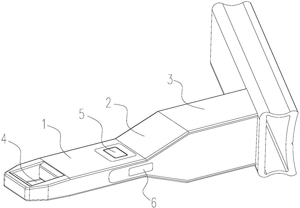
[0040] like figure 1 As shown, the present invention provides a first embodiment of a coupling, including:

[0041] The main body has a cavity in the main body; the main body includes the first part 1, the second part 2 and the third part 3 of an integrated structure, the left and right width of the first part 1 is 1 cm, the left and right width of the third part 3 is 5 cm, and the second part 2 It is in the shape of a square prism and connected between the first part 1 and the third part 3. The car lock also has an entrance similar to the second part 2. The entrance communicates with the lockway, and the first part 1 is inserted into the lockway from the entrance. At the same time, the entrance can fit the second part 2 to play the effect of limiting and stopping; the front end of the first part 1 is provided with a lock hole 4, and the lock hole 4 is a square hole penetrating the first part 1 from left to right;

[0042]Charging module, the left charging contact 5 of the ch...

Embodiment 2

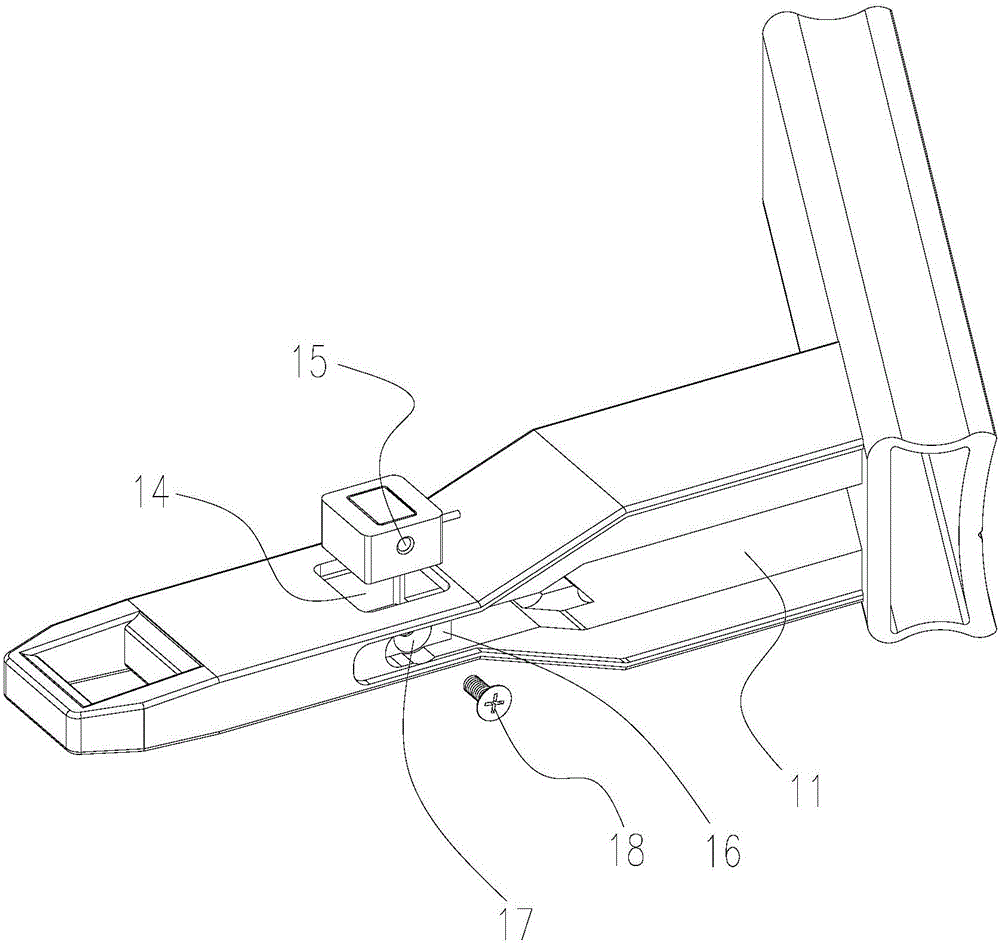
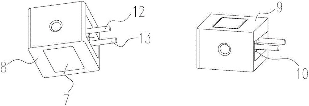
[0045] The present invention also provides a second embodiment of a coupler. Compared with the first embodiment, a specific structure of the charging module is provided in the second embodiment, such as Figure 2~3 As shown, the left charging contact 5 and the right charging contact 7 are rectangular copper sheets, and the charging module also includes:

[0046] Cylindrical housing, the cylindrical housing is a cuboid-shaped plastic part with an integrated structure, and the right side panel 8 of the cylindrical housing is provided with a right rectangular hole consistent with the outer contour of the right charging contact 7, and the right charging contact 7 is set In the right rectangular hole, the right side panel 8 is tightly wrapped on the right charging contact 7 to form an insulating layer, and the left side panel 9 of the cylindrical shell is provided with a left rectangular hole consistent with the outer contour of the left charging contact 5 , the left charging conta...


PUM


Abstract

The invention provides a coupler. The coupler comprises a body, an electronic tag, a charging module and an infrared communication module, wherein a cavity is formed in the body, the electronic tag is fixed in the cavity, a left charging contact of the charging module is exposed on the left side face of the body, a right charging contact is exposed on the right side face of the body, and the infrared communication module is exposed on the surface of the body. The coupler integrates the four functions of locking, charging, communication and identity recognition, a locking device which has locking and identity recognition functions only and is used on an original common boosting bicycle is improved, the two contacts of the charging module are arranged on the left side face and the right side face of the body respectively, the possibility that the two contacts are in short circuit due to rainwater is reduced, the coupler is basically the same as the locking device used in the common boosting bicycle in appearance, the old-fashioned locker can be applied to a leasing system of electric boosting bicycles just by being transformed slightly, and transformation cost and difficulty are reduced.

Description

technical field [0001] The invention relates to the technical field of power-assisted bicycles, in particular to a power-assisted bicycle and a coupling thereof. Background technique [0002] Power-assisted bicycles are the most popular means of transportation in my country, and their ownership is the largest in the world. Public power-assisted bicycles, as a low-carbon, environmentally friendly and green transportation mode, have already occupied an important place in the urban public transportation system. . [0003] Electric power-assisted bicycles are based on ordinary power-assisted bicycles. They are products that combine machinery, electronics, software and magnetism. The control system uses dual magnetic circuits (active magnetic circuit and passive magnetic circuit)-Hall elastic angle difference counting, detection The dynamic torque generated when people step on it converts the dynamic torque signal into a digital signal, and then converts it into an analog signal ...

Claims


Application Information

Patent Timeline
IPC IPC(8): B62H5/00B60L11/18
CPCB60L53/16B62H5/00Y02T10/70Y02T10/7072Y02T90/14Y02T90/16
Inventor 黄得云殷振亚李永强仄伟杰王珏
Owner YOUON TECH CO LTD
Learn More