
Terminal equipment

A terminal equipment, one-sided technology, applied in the direction of electrical components, magnetic field/electric field shielding, etc., can solve the problems of unfavorable electronic equipment thickness, reduction, occupied area, etc.

Inactive Publication Date: 2016-08-03
QINGDAO HISENSE MOBILE COMM TECH CO LTD
View PDF7 Cites 13 Cited by
  • Summary
  • Abstract
  • Description
  • Claims
  • Application Information

AI Technical Summary

Problems solved by technology

[0003] One of the usual methods in the prior art is to paste the fingerprint recognition module on the back shell of the electronic device through glue; another method is to directly fix it on the main board through a re-layout device arrangement; but no matter which method is used Both methods will affect the original devices on the main board, such as microprocessors, graphics cards and other devices. When the first method is used, since the fingerprint recognition module is fixed on the rear case during assembly, no matter where it is pasted on the rear case will overlap with the original devices on the main board, especially when considering the influence of electromagnetic shielding on some original devices, it is necessary to design a shielding cover on the periphery of the device separately, and paste the fingerprint recognition module on the corresponding device with a shielding cover. When the rear case is on, the thicknesses of the structures above the above-mentioned devices are superimposed on each other, which is not conducive to reducing the thickness of the electronic equipment. When using the second method, it is first necessary to redesign the layout taking into account the original device and the fingerprint recognition module. The circuit of the fingerprint identification module will occupy a certain area on the motherboard, which is not conducive to the miniaturization of the motherboard

Method used


Image

  • Terminal equipment
  • Terminal equipment
  • Terminal equipment

Examples

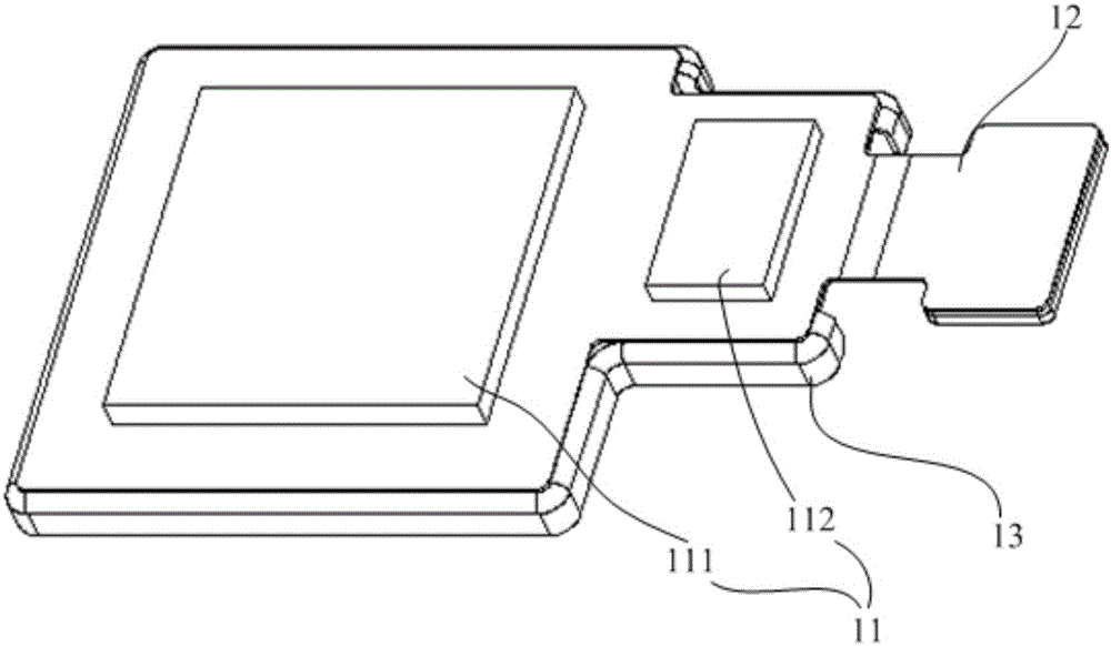

Embodiment Construction

[0026] The following will clearly and completely describe the technical solutions in the embodiments of the present invention with reference to the accompanying drawings in the embodiments of the present invention. Obviously, the described embodiments are only some, not all, embodiments of the present invention. Based on the embodiments of the present invention, all other embodiments obtained by persons of ordinary skill in the art without making creative efforts belong to the protection scope of the present invention.

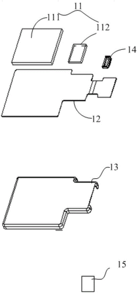
[0027] The embodiment of the present invention is applied to a terminal device. The terminal device can be a mobile phone, a computer, a smart TV, etc. that include a fingerprint identification module. This solution is used for the assembly of a fingerprint identification module. The specific principle is that the fingerprint identification module The patch is installed on one side of the FPC (FlexiblePrintedCircuitboard, disruptive substrate or bypass printed ...


PUM


Abstract

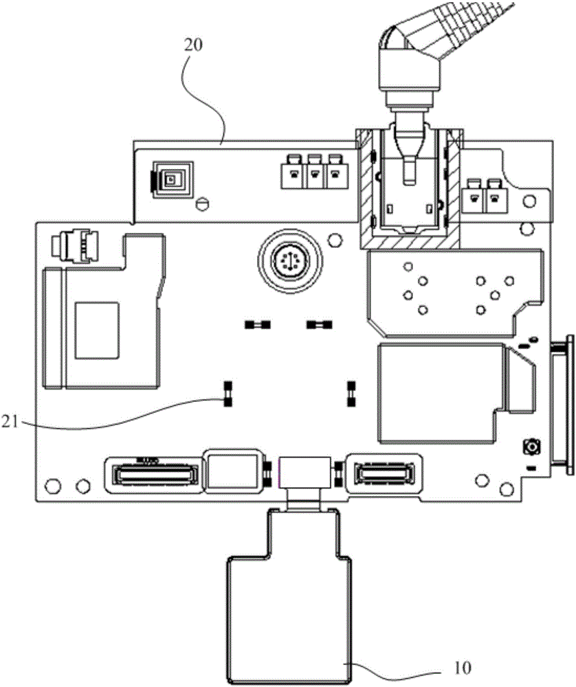
The embodiment of the invention discloses terminal equipment, and relates to the electronic equipment field. The terminal equipment can consider the thickness of a whole machine at a fingerprint identification module and does not influence the board utilization rate of a main board. The terminal equipment includes a fingerprint identification module, a flexible printed circuitboard FPC and a main board, wherein the fingerprint identification module is pasted on one surface of the FPC; the other surface of the FPC is pasted on a reinforced sheet layer; the reinforced sheet layer is fixed on the main board, and is used for reinforcement of the FPC; and the reinforced sheet layer is also used for shielding a device on the main board. The embodiment of the terminal equipment is used for assembling of terminal equipment.

Description

technical field [0001] The present invention relates to the field of electronic equipment, in particular to a terminal equipment. Background technique [0002] With the ultra-thinning of electronic equipment, the PCB (Printed Circuit Board, printed circuit board) board used as the main board of electronic equipment is developing toward integration and ultra-minimization. When new functions need to be integrated, it is often necessary to redevelop a new PCB layout design . For example, when designing the fingerprint recognition function, it is necessary to consider occupying a smaller device area and thickness. [0003] One of the usual methods in the prior art is to paste the fingerprint recognition module on the back shell of the electronic device through glue; another method is to directly fix it on the main board through a re-layout device arrangement; but no matter which method is used Both methods will affect the original devices on the main board, such as microproces...

Claims


Application Information

Patent Timeline
IPC IPC(8): H05K9/00
CPCH05K9/0024
Inventor 徐世慧
Owner QINGDAO HISENSE MOBILE COMM TECH CO LTD
Learn More