
Tunnel siphon water drainage system and construction method thereof

A technology of drainage system and construction method, which is applied in the directions of drainage, earthwork drilling, safety devices, etc., can solve the problems of water seepage, increased water pressure, increase, etc., and achieves a small damage slope, simple construction method, and convenient maintenance. Effect

Inactive Publication Date: 2016-08-03
TONGJI UNIV
View PDF5 Cites 14 Cited by
  • Summary
  • Abstract
  • Description
  • Claims
  • Application Information

AI Technical Summary

Problems solved by technology

In the actual use process, there are certain defects in the waterproof board isolation layer of this structure. For example, in the tunnels of the IV, V, and VI surrounding rocks, as time goes by, the tiny particles in the surrounding rocks accumulate day by day, making the geotextile non-woven The cloth is hardened and cannot filter, so that the water behind the tunnel lining cannot flow smoothly into the drain pipe
The survey found that most of the water seepage in the tunnel lining is due to the fact that the drainage pipes installed in the lining do not produce water, which cannot meet the drainage requirements, and sedimentation occurs in the pipes, the water behind the lining corrodes the lining, or the amount of water accumulated behind the tunnel lining increases, and the water pressure increases. , resulting in water seepage or cracking at weak lining quality

Method used


Image

  • Tunnel siphon water drainage system and construction method thereof
  • Tunnel siphon water drainage system and construction method thereof

Examples


Embodiment 1

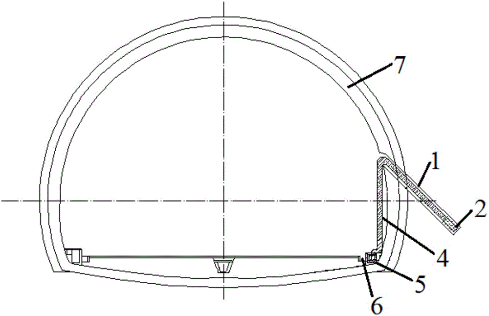
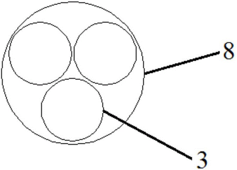
[0033] A tunnel siphon drainage system, the drainage system includes a borehole 1 set at the seepage point of the tunnel wall 7 and inclined downwards, a water reservoir 2 arranged at the bottom of the borehole 1, and a siphon sleeve connected to the water reservoir 2 in sequence Pipe 4, water storage barrel 5 and longitudinal drainage ditch 6, the angle between the borehole 1 and the vertical direction is 45°, one end of the siphon sleeve 4 is inserted into the borehole 1 and communicated with the water storage 2, and the other end is connected to the borehole 1 One place is drawn vertically and placed in the water storage barrel 5, and the water outlet of the siphon sleeve 4 is 40cm lower than the position of the water reservoir 2.

[0034] The borehole 1 is opened at the side wall of the tunnel cross section at the water seepage point of the tunnel wall 7, and the borehole 1 is 1.0m higher than the bottom of the tunnel. The borehole 1 has a diameter of 35mm and a length of ...

Embodiment 2

[0049] A tunnel siphon drainage system, the drainage system includes a borehole 1 set at the seepage point of the tunnel wall 7 and inclined downwards, a water reservoir 2 arranged at the bottom of the borehole 1, and a siphon sleeve connected to the water reservoir 2 in sequence Tube 4, water storage barrel 5 and longitudinal drainage ditch 6, the angle between borehole 1 and the vertical direction is 75°, one end of siphon sleeve 4 is inserted into borehole 1 and communicated with water storage 2, and the other end is connected to the borehole One place is drawn vertically and placed in the water storage bucket 5, and the water outlet of the siphon sleeve 4 is 60cm lower than the position of the water storage tank 2.

[0050] The borehole 1 is opened at the side wall of the tunnel cross section at the seepage point of the tunnel wall 7, and the borehole 1 is 1.5m higher than the bottom of the tunnel. Borehole 1 has a diameter of 45 mm and a length of 2.0 m.

[0051] The sip...

Embodiment 3

[0062] A tunnel siphon drainage system, the drainage system includes a borehole 1 set at the seepage point of the tunnel wall 7 and inclined downwards, a water reservoir 2 arranged at the bottom of the borehole 1, and a siphon sleeve connected to the water reservoir 2 in sequence Tube 4, water storage barrel 5 and longitudinal drainage ditch 6, the angle between borehole 1 and the vertical direction is 60°, one end of siphon sleeve 4 is inserted into borehole 1 and communicated with water storage 2, and the other end is connected with the borehole One place is drawn vertically and placed in the water storage bucket 5, and the water outlet of the siphon sleeve 4 is 50cm lower than the position of the water storage tank 2.

[0063] The borehole 1 is opened at the side wall of the tunnel cross section at the seepage point of the tunnel wall 7, and the borehole 1 is 1.2m higher than the bottom of the tunnel. The borehole 1 has a diameter of 42mm and a length of 1.8m.

[0064] The...


PUM


Abstract

The invention relates to a tunnel siphon water drainage system and a construction method thereof. The water drainage system comprises a drilling hole which is formed in a water seepage point in the wall of a tunnel, a water reservoir arranged on the bottom of the drilling hole, a siphon sleeve communicated with the water reservoir, a water storage barrel and a longitudinal water drainage ditch, wherein an included angle between the drilling hole and a vertical direction is 45-75 degrees; one end of the siphon sleeve is inserted into the drilling hole and is communicated with the water reservoir, and the other end of the siphon sleeve is vertically guided out from the drilling hole, and is arranged in the water storage barrel; a water outlet of the siphon sleeve is lower than the water reservoir by 40-60 cm; during construction, drilling is firstly carried out, the water reservoir and the water storage barrel are arranged, and the two ends of the siphon sleeve are separately inserted into the water reservoir and the water storage barrel. Compared with the prior art, the tunnel siphon water drainage system has the advantages that underground water near the water seepage point in the tunnel wall can be discharged timely, power is not needed to be additionally provided in a water drainage process, water drainage flow and a flow process are automatically controlled by water level changes, and smooth water drainage is effectively guaranteed.

Description

technical field [0001] The invention belongs to the technical field of tunnel and underground engineering waterproof and drainage, and relates to a tunnel siphon drainage system and a construction method thereof. Background technique [0002] The tunnel waterproof and drainage design follows the principle of "prevention, drainage, interception, blocking, adapting measures to local conditions, and comprehensive treatment". The existing waterproof and drainage structure is mainly to set geotechnical non-woven fabric and The flexible waterproof layer of the waterproof board, wherein the waterproof board also serves as the isolation layer. In the actual use process, there are certain defects in the waterproof board isolation layer of this structure. For example, in the tunnels of the IV, V, and VI surrounding rocks, as time goes by, the tiny particles in the surrounding rocks accumulate day by day, making the geotextile non-woven The cloth was hardened and could not filter, so ...

Claims


Application Information

Patent Timeline
Patent Type & Authority Applications(China)
IPC IPC(8): E21F16/02
CPCE21F16/02
Inventor 许建聪金彩虹
Owner TONGJI UNIV
Learn More